1KHz Sine Wave Signal Generator 1000Hz High Precision Signal Generators Low Distortion Oscillator Circuit Board
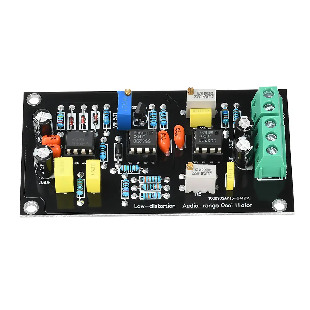
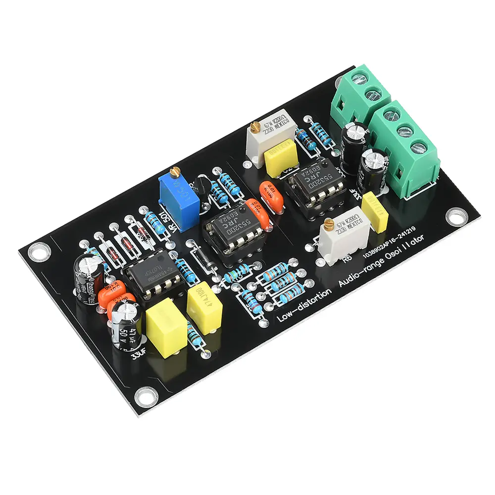
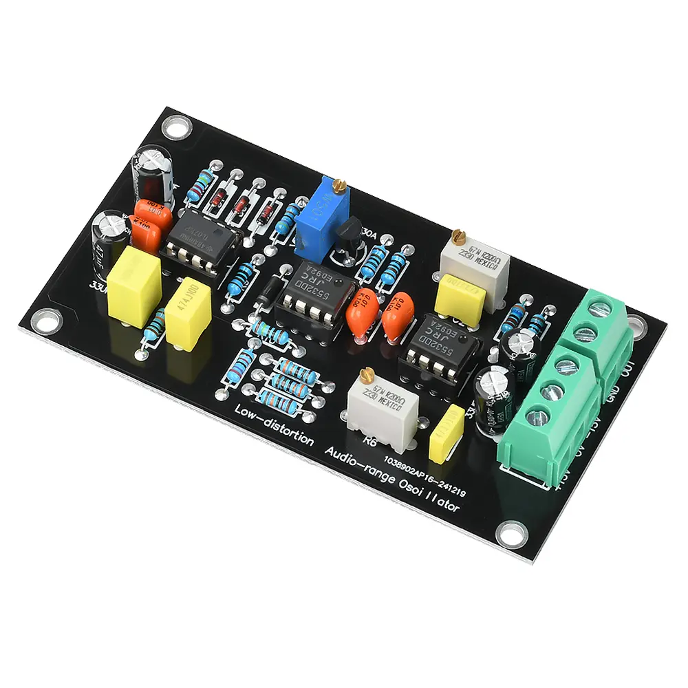
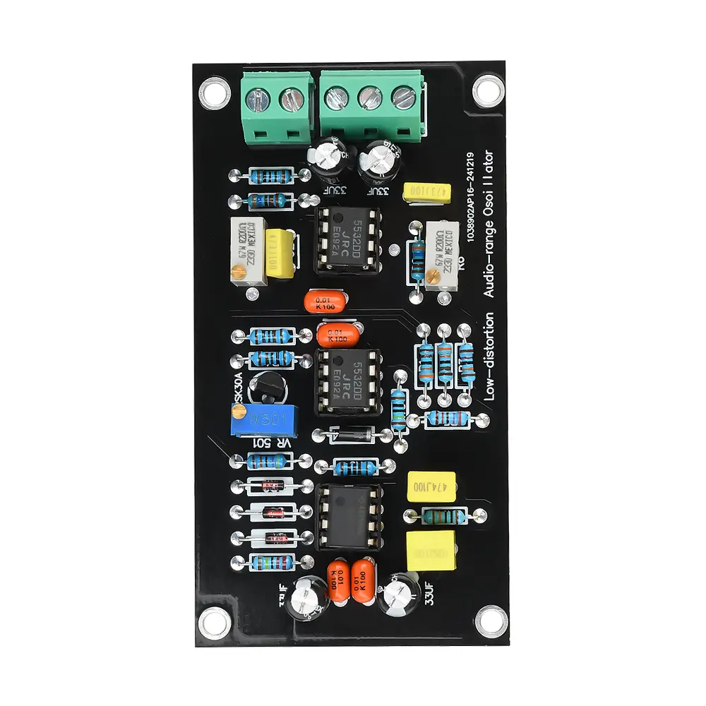
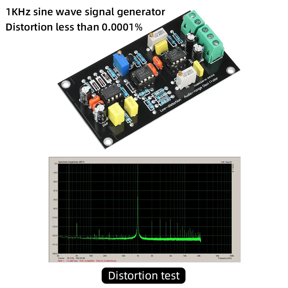
<div class="detailmodule_html"><div class="detail-desc-decorate-richtext"><p>Feature: <br />1.1KHz sine wave output with a distortion coefficient of only 0.000064%, suitable for high-precision testing applications. <br />2. Ultra low distortion design, with distortion less than 0.001%, ensuring signal purity and stability. <br />3. The power supply is ± 15V, with a current of only 30mA, making low-power operation more efficient and energy-saving. <br />4. Output voltage greater than 7V, suitable for harmonic distortion testing, level testing, and regenerative power supply scenarios. <br />5. Adopting the NE5532 chip, it has good performance and effective use.</p>
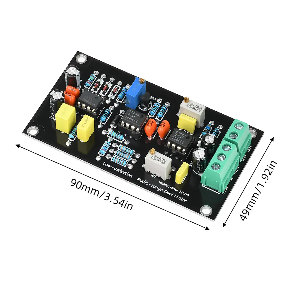
<p>Product parameters: <br />Power supply: ± 15V, 30mA <br />Output voltage: greater than 7V <br />Distortion: less than 0.001% <br />Dimensions: 90 * 49mm * 16mm</p>
<p>Product Description: <br />Low distortion coefficient sine wave oscillator circuit board, oscillation frequency: 1 KHz, ultra-low distortion, distortion coefficient 0.000064% (-124dB). Can be used for harmonic distortion testing, level testing, regenerative power supply, etc. <br />The capacitors that control the oscillation frequency on the board are selected and paired using a digital meter. The resistor that controls the oscillation frequency is a 3.3K resistor and a 200 ohm 3296 multi turn potentiometer connected in series. The pairing is adjusted by measuring with a digital meter to ensure the accuracy and low distortion of the output frequency.</p>
<p>matters needing attention: <br />In theory, R10=2R13, C3=2C4, Minimal distortion. <br />2. The data in the figure is a value of 1KHZ. If there are other frequencies, besides R6, R7, C1, and C2 that need to be adjusted accordingly, R11 should also be modified according to the frequency. <br />For example: 50HZ, R11=447K, 60HZ, R11=408K.</p>
<p>Product List: <br />1X module<br /></p></div></div>
$46.61
$21.185
- Category : Consumer Electronics
- Brand : diy_electronics_module_999_store DIY Electronics Module 999 Store
Colors
Sizes
-
+
<div class="detailmodule_html"><div class="detail-desc-decorate-richtext"><p>Feature: <br />1.1KHz sine wave output with a distortion coefficient of only 0.000064%, suitable for high-precision testing applications. <br />2. Ultra low distortion design, with distortion less than 0.001%, ensuring signal purity and stability. <br />3. The power supply is ± 15V, with a current of only 30mA, making low-power operation more efficient and energy-saving. <br />4. Output voltage greater than 7V, suitable for harmonic distortion testing, level testing, and regenerative power supply scenarios. <br />5. Adopting the NE5532 chip, it has good performance and effective use.</p>
<p>Product parameters: <br />Power supply: ± 15V, 30mA <br />Output voltage: greater than 7V <br />Distortion: less than 0.001% <br />Dimensions: 90 * 49mm * 16mm</p>
<p>Product Description: <br />Low distortion coefficient sine wave oscillator circuit board, oscillation frequency: 1 KHz, ultra-low distortion, distortion coefficient 0.000064% (-124dB). Can be used for harmonic distortion testing, level testing, regenerative power supply, etc. <br />The capacitors that control the oscillation frequency on the board are selected and paired using a digital meter. The resistor that controls the oscillation frequency is a 3.3K resistor and a 200 ohm 3296 multi turn potentiometer connected in series. The pairing is adjusted by measuring with a digital meter to ensure the accuracy and low distortion of the output frequency.</p>
<p>matters needing attention: <br />In theory, R10=2R13, C3=2C4, Minimal distortion. <br />2. The data in the figure is a value of 1KHZ. If there are other frequencies, besides R6, R7, C1, and C2 that need to be adjusted accordingly, R11 should also be modified according to the frequency. <br />For example: 50HZ, R11=447K, 60HZ, R11=408K.</p>
<p>Product List: <br />1X module<br /></p></div></div>