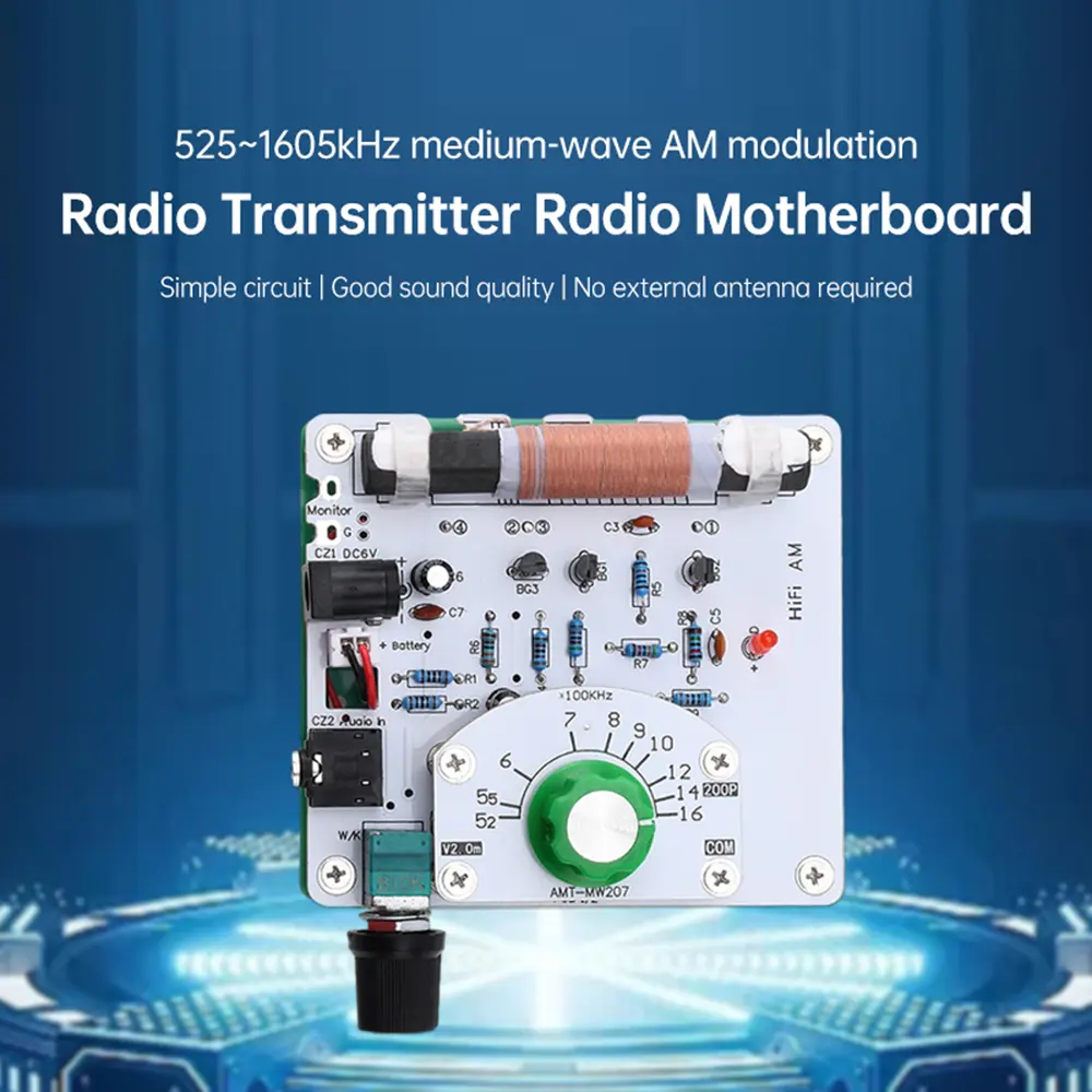
525~1605kHz MW AM AM Radio Transmitter DIY Circuit Board Amplitude Modulation Radio Transmitter Ore radio Mother Board 6V
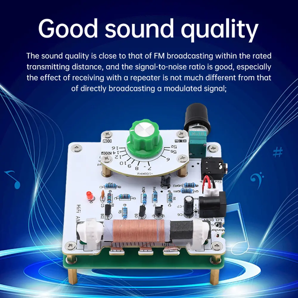
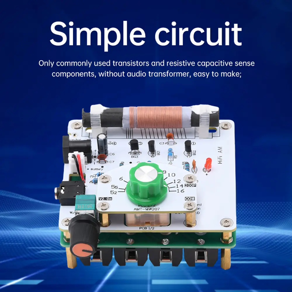
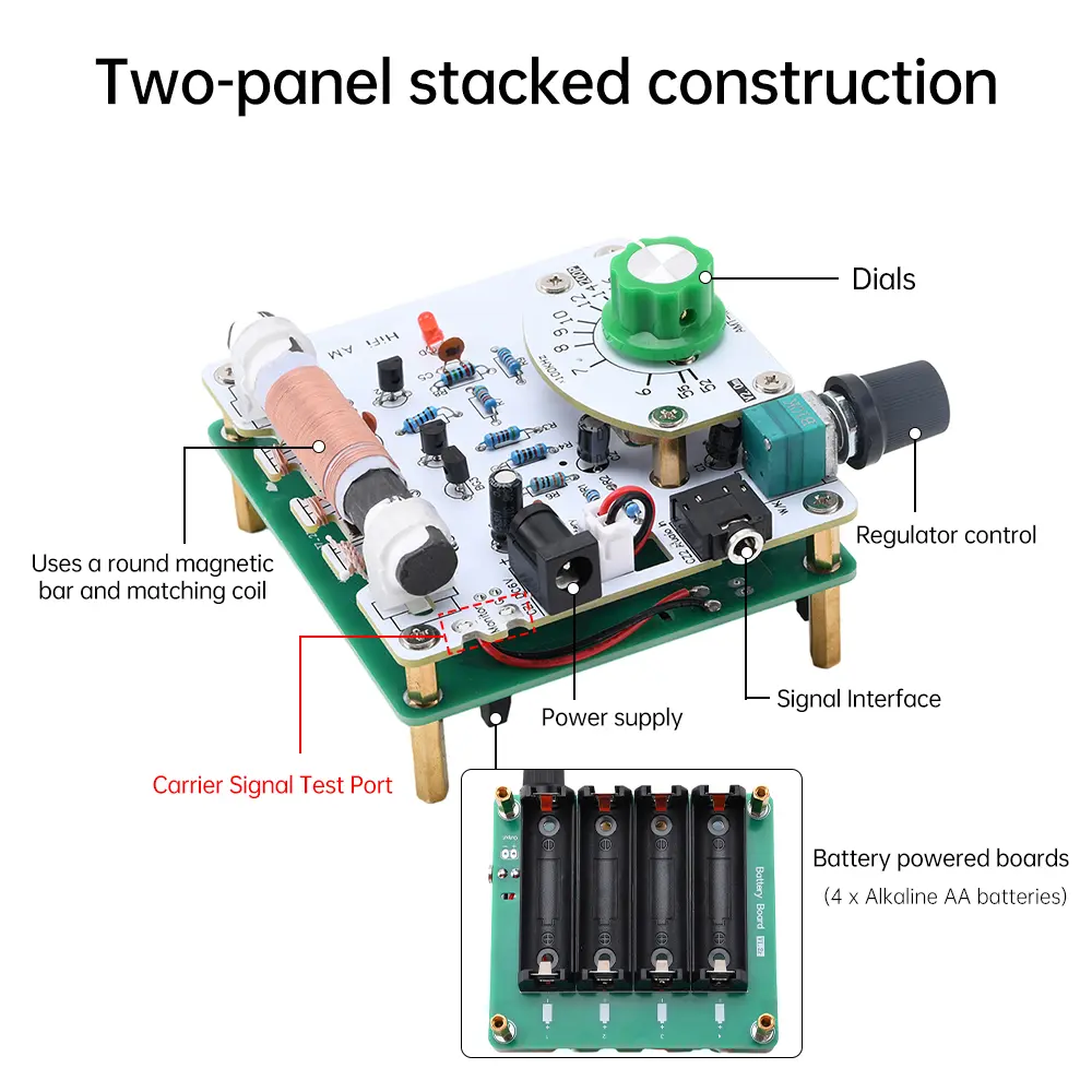
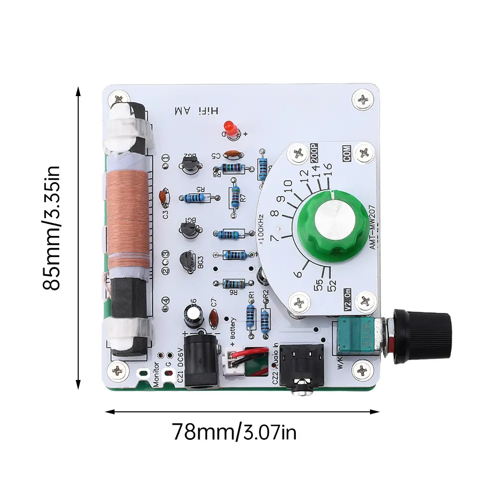
<div class="detailmodule_html"><div class="detail-desc-decorate-richtext"><p>Features: <br/>1. The circuit is simple. Only commonly used transistors and resistive capacitive sensing components are used, without the need for an audio transformer, making it easy to manufacture; <br/>2. Good sound quality. Within the rated transmission distance, the sound quality is close to FM radio, with good signal-to-noise ratio, especially when received by a repeater, the effect is not much different from directly playing modulated signals; <br/>3. Without the need for an external antenna (medium wave requires tens of meters), the receiver is completely affected by the magnetic field leaked by the magnetic rod, which is easy to implement and has a relatively short transmission distance; <br/>4. Multiple interfaces, designed with waveform testing terminals, audio sockets, external power sockets, etc., for easy use and expansion of functions; <br/>5. It can be connected to an external power source and also installed with a battery for independent use.</p><p>Parameter: <br/>Frequency range: 525~1605kHz <br/>Supply voltage: 6V <br/>DC power interface: 5.5 * 2.1mm <br/>Circuit board size: 78mmx85mm (length x width) <br/>Transmission distance: about 1 meter for superheterodyne medium wave radio, about 0.5 meters for direct and mineral radio</p><p>Package include: <br/>1X module <br/>1X3.5mm headphone signal cable</p><p>Product Introduction: <br/>1. This kit adopts fully discrete circuit components, which is particularly suitable for students to learn working principles, practice production and testing; <br/>2. Variable capacitors use dual variable capacitors, which are connected in parallel to obtain sufficient capacity; <br/>3. Adopting double-sided board circuit, the board base is made of fiberglass material, with a measured thickness of about 1.5-1.6mm. The solder pads are treated with tin spraying and can be directly welded without polishing; <br/>4. This product has undergone n modifications and improvements so far (mainly modifying the wiring of the circuit board and keeping the circuit unchanged), and is still being continuously improved. Usually minor non substantial modifications, such as slight movement of component positions or adjustments to wiring, will not change the version number, nor will they be re photographed and uploaded. This is hereby declared; <br/>5. The manual contains circuit schematics and circuit board diagrams, as well as debugging methods and experience under amateur conditions. If more information and professional debugging methods are needed, buyers can download or refer to relevant professional books online; Mainly due to changes in component positions, the circuit structure remains unchanged. <br/>6. The transmitter is equipped with a 3.5mm headphone signal cable, which does not include a battery. <br/>Usage effect: This transmitter works very well within an effective distance (0.5~1 meter), with high sound fidelity. Especially when used with a direct broadcast radio (such as 636 and 68-1 single tube units) and high impedance dynamic coil headphones, the sound quality is not much different from that of a player playing directly. <br/>instructions: <br/>1. Insert an external 6V DC power supply (positive inside and negative outside) into the CZ1 socket on the board, or plug the 6V battery pack connector into the Battery interface, being careful not to confuse the positive and negative poles. <br/>2. Insert the signal cable into the CZ2 socket on the circuit board and connect it to the modulation signal source. The signal source can be a mobile phone, player, etc. It is recommended to use a player because mobile phones have strong interference with medium wave radios. <br/>3. Turn the potentiometer knob to turn on the device, which has a similar effect to the volume potentiometer on a radio. <br/>4. Turn on the radio and search for the signal from the transmitter to listen. You can also operate in reverse by adjusting the radio reception frequency to a position without a radio station, and then turning the transmitter dial to change the transmission frequency until the radio plays the signal from the transmitter.</p><p>Usage restrictions: <br/>1. This product only has a good effect within the desktop range. When the radio is too far away from the transmitter (more than 1 meter), the effect will seriously decline, manifested as low sound and deteriorating signal-to-noise ratio; <br/>2. Increasing the supply voltage can significantly increase the waveform amplitude, but the actual usable transmission distance does not change much; <br/>3. The potentiometer of the transmitter controls the modulation degree. If the modulation is too large, it will cause distortion in the radio demodulation and the waveform of the transmitter itself will also deteriorate. The correct usage is to summarize a suitable position after multiple uses, so that the modulation degree can be as large as possible and the sound quality can be guaranteed as much as possible. Turn it to this position every time you use it, and do not use it as a volume potentiometer for the radio to frequently adjust it.</p><p>Usage precautions: <br/>1. Due to the asymmetry between the two sides of the circuit board (especially the single panel), there may be slight natural bending, which has no impact on normal use. There may be some scratches, dust, and washing marks on the base surface and copper foil surface of the board; <br/>2. Due to the fact that printed circuit board manufacturers mainly produce multi-layer boards (double-sided boards and multi-layer boards), they are not familiar with the characteristics of amateur DIY single panels and often treat single panels as multi-layer boards by metalizing hole walls. Generally, a single panel does not require metalized hole walls, but if there are metalized hole walls, it is not a fatal error and will not have any impact on the normal operation of the circuit. However, when soldering components, higher soldering power is required and the soldering iron temperature needs to be increased; <br/>3. The copper foil of the circuit board is bonded to the substrate with adhesive. Prolonged, repeated, or multiple soldering can cause the copper foil to peel off; <br/>4. Some of the organic thin film variable capacitors have been in stock for a long time, with a gray layer on the outer shell and oxidized leads. Slight treatment is sufficient and does not affect their use; <br/>5. Ordinary grade ceramic capacitors (such as Y5V) have a large error, with a nominal error of up to+80% -20%. They have poor temperature stability and are suitable for applications with low requirements such as filtering and coupling; <br/>6. The antenna magnetic rod is slightly bent, and the larger the size, the more obvious it is, but it has no effect on the performance of use. The texture of the antenna magnetic rod is very brittle, and it will break upon impact.<br/><br/></p></div></div><p><br/></p>
$62.315
$36.98
- Category : Home Improvement
- Brand : z_industry_store Z Industry Store
Colors
Sizes
-
+
<div class="detailmodule_html"><div class="detail-desc-decorate-richtext"><p>Features: <br/>1. The circuit is simple. Only commonly used transistors and resistive capacitive sensing components are used, without the need for an audio transformer, making it easy to manufacture; <br/>2. Good sound quality. Within the rated transmission distance, the sound quality is close to FM radio, with good signal-to-noise ratio, especially when received by a repeater, the effect is not much different from directly playing modulated signals; <br/>3. Without the need for an external antenna (medium wave requires tens of meters), the receiver is completely affected by the magnetic field leaked by the magnetic rod, which is easy to implement and has a relatively short transmission distance; <br/>4. Multiple interfaces, designed with waveform testing terminals, audio sockets, external power sockets, etc., for easy use and expansion of functions; <br/>5. It can be connected to an external power source and also installed with a battery for independent use.</p><p>Parameter: <br/>Frequency range: 525~1605kHz <br/>Supply voltage: 6V <br/>DC power interface: 5.5 * 2.1mm <br/>Circuit board size: 78mmx85mm (length x width) <br/>Transmission distance: about 1 meter for superheterodyne medium wave radio, about 0.5 meters for direct and mineral radio</p><p>Package include: <br/>1X module <br/>1X3.5mm headphone signal cable</p><p>Product Introduction: <br/>1. This kit adopts fully discrete circuit components, which is particularly suitable for students to learn working principles, practice production and testing; <br/>2. Variable capacitors use dual variable capacitors, which are connected in parallel to obtain sufficient capacity; <br/>3. Adopting double-sided board circuit, the board base is made of fiberglass material, with a measured thickness of about 1.5-1.6mm. The solder pads are treated with tin spraying and can be directly welded without polishing; <br/>4. This product has undergone n modifications and improvements so far (mainly modifying the wiring of the circuit board and keeping the circuit unchanged), and is still being continuously improved. Usually minor non substantial modifications, such as slight movement of component positions or adjustments to wiring, will not change the version number, nor will they be re photographed and uploaded. This is hereby declared; <br/>5. The manual contains circuit schematics and circuit board diagrams, as well as debugging methods and experience under amateur conditions. If more information and professional debugging methods are needed, buyers can download or refer to relevant professional books online; Mainly due to changes in component positions, the circuit structure remains unchanged. <br/>6. The transmitter is equipped with a 3.5mm headphone signal cable, which does not include a battery. <br/>Usage effect: This transmitter works very well within an effective distance (0.5~1 meter), with high sound fidelity. Especially when used with a direct broadcast radio (such as 636 and 68-1 single tube units) and high impedance dynamic coil headphones, the sound quality is not much different from that of a player playing directly. <br/>instructions: <br/>1. Insert an external 6V DC power supply (positive inside and negative outside) into the CZ1 socket on the board, or plug the 6V battery pack connector into the Battery interface, being careful not to confuse the positive and negative poles. <br/>2. Insert the signal cable into the CZ2 socket on the circuit board and connect it to the modulation signal source. The signal source can be a mobile phone, player, etc. It is recommended to use a player because mobile phones have strong interference with medium wave radios. <br/>3. Turn the potentiometer knob to turn on the device, which has a similar effect to the volume potentiometer on a radio. <br/>4. Turn on the radio and search for the signal from the transmitter to listen. You can also operate in reverse by adjusting the radio reception frequency to a position without a radio station, and then turning the transmitter dial to change the transmission frequency until the radio plays the signal from the transmitter.</p><p>Usage restrictions: <br/>1. This product only has a good effect within the desktop range. When the radio is too far away from the transmitter (more than 1 meter), the effect will seriously decline, manifested as low sound and deteriorating signal-to-noise ratio; <br/>2. Increasing the supply voltage can significantly increase the waveform amplitude, but the actual usable transmission distance does not change much; <br/>3. The potentiometer of the transmitter controls the modulation degree. If the modulation is too large, it will cause distortion in the radio demodulation and the waveform of the transmitter itself will also deteriorate. The correct usage is to summarize a suitable position after multiple uses, so that the modulation degree can be as large as possible and the sound quality can be guaranteed as much as possible. Turn it to this position every time you use it, and do not use it as a volume potentiometer for the radio to frequently adjust it.</p><p>Usage precautions: <br/>1. Due to the asymmetry between the two sides of the circuit board (especially the single panel), there may be slight natural bending, which has no impact on normal use. There may be some scratches, dust, and washing marks on the base surface and copper foil surface of the board; <br/>2. Due to the fact that printed circuit board manufacturers mainly produce multi-layer boards (double-sided boards and multi-layer boards), they are not familiar with the characteristics of amateur DIY single panels and often treat single panels as multi-layer boards by metalizing hole walls. Generally, a single panel does not require metalized hole walls, but if there are metalized hole walls, it is not a fatal error and will not have any impact on the normal operation of the circuit. However, when soldering components, higher soldering power is required and the soldering iron temperature needs to be increased; <br/>3. The copper foil of the circuit board is bonded to the substrate with adhesive. Prolonged, repeated, or multiple soldering can cause the copper foil to peel off; <br/>4. Some of the organic thin film variable capacitors have been in stock for a long time, with a gray layer on the outer shell and oxidized leads. Slight treatment is sufficient and does not affect their use; <br/>5. Ordinary grade ceramic capacitors (such as Y5V) have a large error, with a nominal error of up to+80% -20%. They have poor temperature stability and are suitable for applications with low requirements such as filtering and coupling; <br/>6. The antenna magnetic rod is slightly bent, and the larger the size, the more obvious it is, but it has no effect on the performance of use. The texture of the antenna magnetic rod is very brittle, and it will break upon impact.<br/><br/></p></div></div><p><br/></p>
Related Product
Browse The Collection of Top Products.