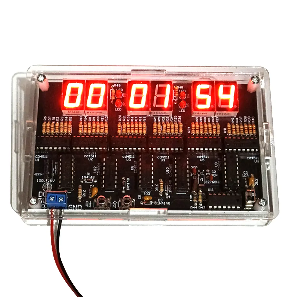
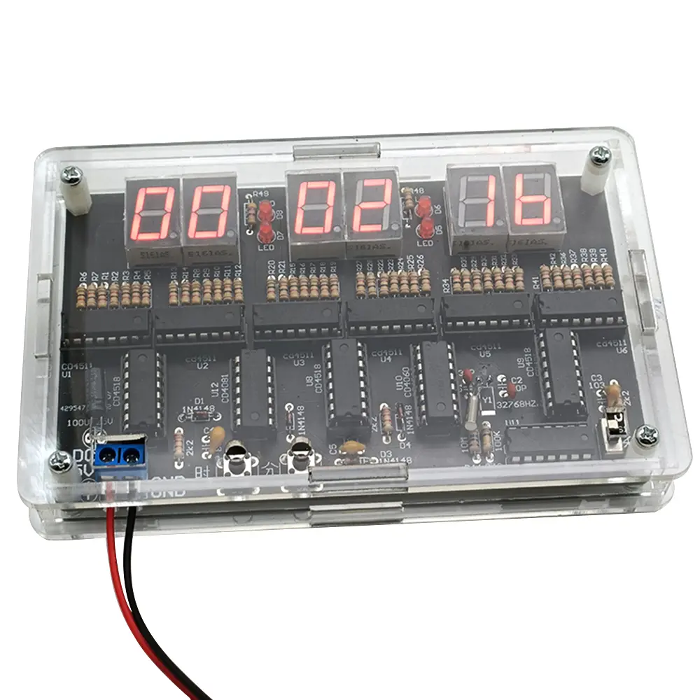
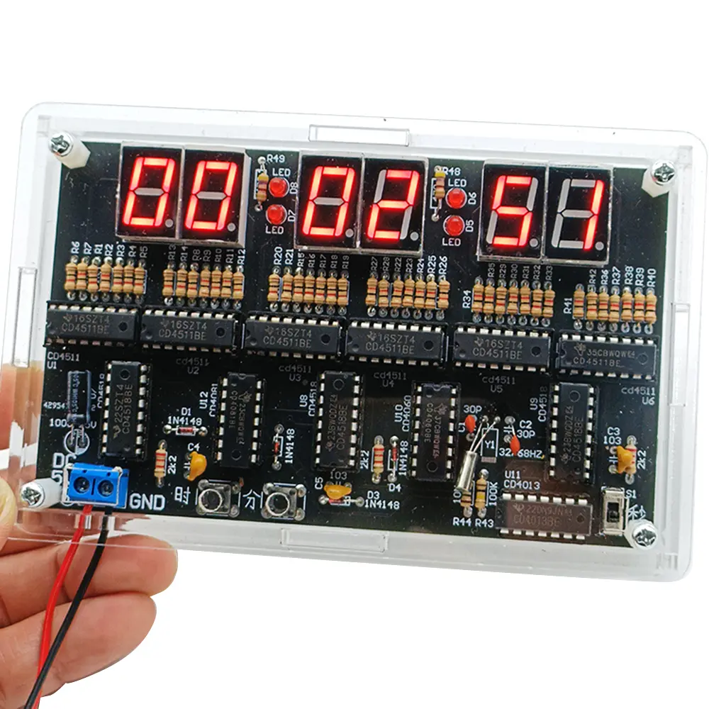
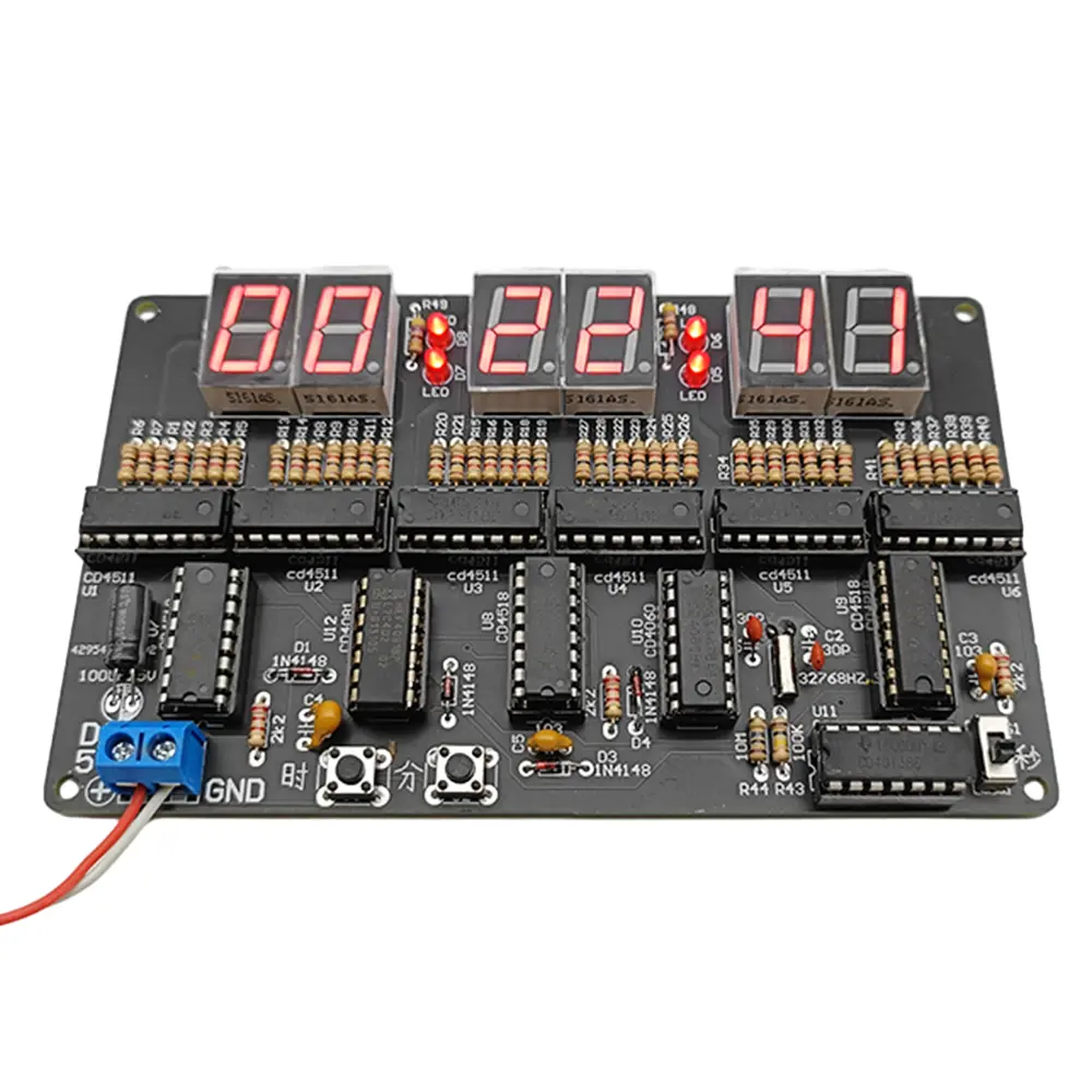
6 Digits DIY Digital Circuit Clock Kit Auto Display Time DIY Alarm Clock Soldering Practice Kit for Students DC 4.5V-5.5V
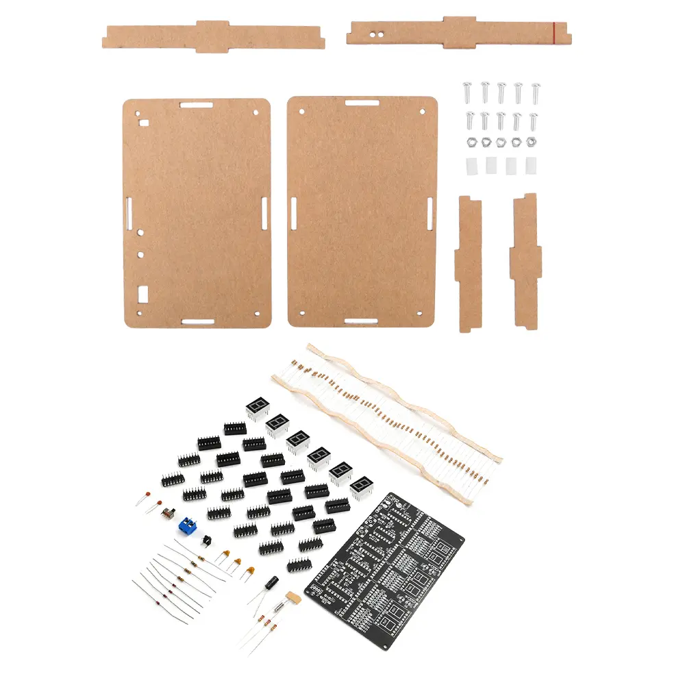
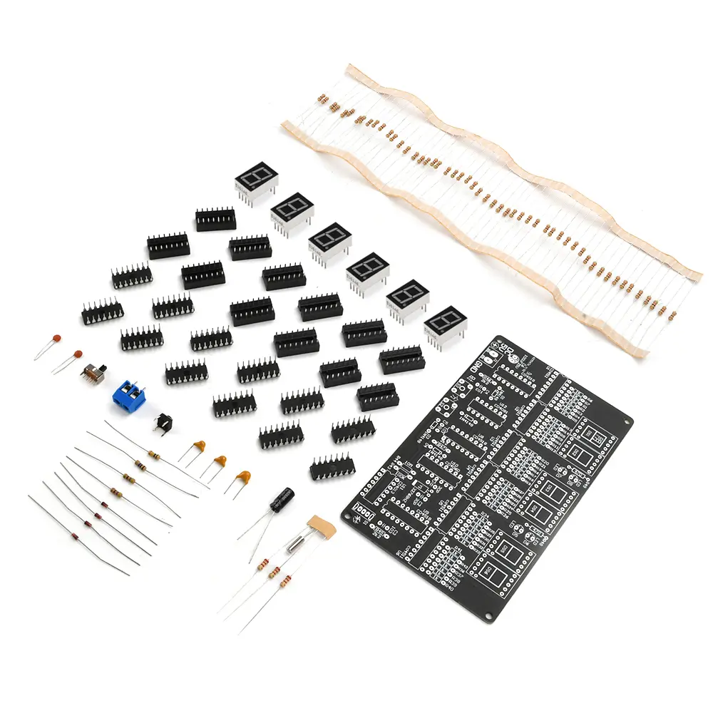
<div class="detailmodule_html"><div class="detail-desc-decorate-richtext"><p><strong><span style="font-size:20px">Parameters:</span></strong><br/>1.This is a 24-hour digital circuit clock kit, using CD4518, CD4511, CD4081, CD4013, CD4060 and other chips<br/>2.The product is made of high quality materials, quality assurance<br/>3. Can be used for teaching and training welding, very suitable for DIY enthusiasts<br/>4.Stable product performance, long service life<br/>5. The use of red digital tube, digital clear at a glance<br/>6. Two specifications are available: with shell and without shell</p><p><strong><span style="font-size:20px">Product Description:</span></strong><br/>This product is a 24-hour digital circuit clock, using CD4518, CD4511, CD4081, CD4013, CD4060 and other chips, the circuit does not contain a microcontroller, so there is no programme, the hours and minutes and seconds can be calibrated, without alarm function.<br/>This kit mainly consists of a second signal generator, counter, decoding display and time calibration circuit. The second pulse is a 1HZ square wave signal obtained by precise frequency division of a high frequency signal generator, which is more accurate in timekeeping.</p><p>The second signal generator consists of CD4060 and CD4013, which generates a square wave signal with a frequency of 1HZ. CD4060 is a 14-level binary frequency divider/oscillator. It consists of a 32768HZ oscillator with external resistors R44, R43, C1, C2 and Y1. After 14 levels of binary frequency divider, the frequency of 2HZ square wave signal is obtained at pin 3. CD4013 contains two independent D flip-flops, take one of the flip-flops through the line configured as a binary counter, binary counting of the input 2HZ square wave signal can be obtained from the second signal. CD4518 is a double-decimal addition counter. The CD4518 is a double-decimal addition counter. 3 CD4518s are used to time the hours, minutes and seconds, the hours are configured as 24, the minutes and seconds are configured as 60. The counting result of the CD4518 is in the form of a BCD code outputted to the BCD decoder CD4511 from the pins Q0-Q3, and the CD4511 converts the BCD code into a display segment code that lights up the corresponding digital tube, and then forms a recognisable Arabic numerals on the digital tube to display the current timing result intuitively. The minutes and seconds are in 60-bit format.</p><p>Minutes and seconds are counted in 60 decimal, the seconds signal is introduced to the EN terminal of CD4518 through switch S1, and 1 is added to the falling edge of each seconds signal (if the seconds signal is connected to the CLK terminal of CD4518, 1 is added to the rising edge of each seconds signal), and when the counter counts up to 9, Q0-Q3 outputs 1001, i.e., Q3 is 1. Since it is a decimal counter, when the next seconds signal arrives, the counter changes from 9 to 0. counter changes from 9 to 0, Q0-Q3 outputs 0000, thus forming a falling edge signal on Q3, this signal is introduced to the ten-digit counter of the second counter, after each full 10 count of the individual counter, the ten-digit counter adds 1. When the ten-digit counter value reaches 6, Q0-Q3 outputs 0110, i.e., Q1 and Q2 are both 1 at the same time, and Q1 and Q2 are connected to the counter through a summing gate and then outputs 1 to the Q1 and Q2 are connected to the reset terminal of the counter through an and gate and output 1, so that the counter counts from 6 to 0 in advance, completing the cycle of 1 hexadecimal counting. The reset signal is also used as the counting signal of the sub-counter, and the sub-counter will be increased by 1 for every full 60 seconds. The sub-counter is also 60-bit, when the sub-counter is full 60, the ten bits of the sub-counter will be reset by a gate, so that the value of the time counter will be increased by 1. When the counter is full 24, the ten bits of the counter will be 0010 and the individual bits of the counter will be 0100, and the ten bits of the counter will be connected to the counter through a gate with an algorithm and Q2. By connecting the Q1 of the tenth bit and the Q2 of the first bit with the algorithm to the reset terminals of the two counters, the hourly bit will be returned to 0 when the counter reaches the full 24, so as to realise the counting of the 24 hexadecimal.</p><p><strong><span style="font-size:20px">DIY loose parts delivery list:</span></strong><br/>PCB board X1<br/>0.56 digital tube 1 bit common negative X6<br/>470 ohm resistor X2<br/>1K resistor X50<br/>2.2K resistor X3<br/>100K Resistor X1<br/>10M resistor X1<br/>1N4148 Diode X4<br/>103 Monolithic Capacitor X3<br/>32.768KHZ crystal X1<br/>30P Porcelain Chip Capacitor X2<br/>25V 100UF Capacitor X1<br/>KF301-2PX1<br/>6*6*5 Keypad X1<br/>12D07 Toggle Switch X1<br/>16P IC Block X10<br/>14P IC Block X 2<br/>CD4511X6<br/>CD4518X3<br/>CD4081X1<br/>CD4060X1<br/>CD4013X1</p><p><strong><span style="font-size:20px">Enclosure shipping list:</span></strong><br/>Acrylic shell X1 set(Optional with or without casing)<br/>M3*8 screws X5<br/>M3*10 screws X5<br/>M3 Nut X5<br/>M3*10 double pass nylon post X4</p><p><strong><span style="font-size:20px">Package include:</span></strong><br/>Loose parts X1<br/></p></div></div><p><br/></p>
$20.285
$9.86
- Category : Consumer Electronics
- Brand : diy_electronics_module_999_store DIY Electronics Module 999 Store
Colors
Sizes
-
+
<div class="detailmodule_html"><div class="detail-desc-decorate-richtext"><p><strong><span style="font-size:20px">Parameters:</span></strong><br/>1.This is a 24-hour digital circuit clock kit, using CD4518, CD4511, CD4081, CD4013, CD4060 and other chips<br/>2.The product is made of high quality materials, quality assurance<br/>3. Can be used for teaching and training welding, very suitable for DIY enthusiasts<br/>4.Stable product performance, long service life<br/>5. The use of red digital tube, digital clear at a glance<br/>6. Two specifications are available: with shell and without shell</p><p><strong><span style="font-size:20px">Product Description:</span></strong><br/>This product is a 24-hour digital circuit clock, using CD4518, CD4511, CD4081, CD4013, CD4060 and other chips, the circuit does not contain a microcontroller, so there is no programme, the hours and minutes and seconds can be calibrated, without alarm function.<br/>This kit mainly consists of a second signal generator, counter, decoding display and time calibration circuit. The second pulse is a 1HZ square wave signal obtained by precise frequency division of a high frequency signal generator, which is more accurate in timekeeping.</p><p>The second signal generator consists of CD4060 and CD4013, which generates a square wave signal with a frequency of 1HZ. CD4060 is a 14-level binary frequency divider/oscillator. It consists of a 32768HZ oscillator with external resistors R44, R43, C1, C2 and Y1. After 14 levels of binary frequency divider, the frequency of 2HZ square wave signal is obtained at pin 3. CD4013 contains two independent D flip-flops, take one of the flip-flops through the line configured as a binary counter, binary counting of the input 2HZ square wave signal can be obtained from the second signal. CD4518 is a double-decimal addition counter. The CD4518 is a double-decimal addition counter. 3 CD4518s are used to time the hours, minutes and seconds, the hours are configured as 24, the minutes and seconds are configured as 60. The counting result of the CD4518 is in the form of a BCD code outputted to the BCD decoder CD4511 from the pins Q0-Q3, and the CD4511 converts the BCD code into a display segment code that lights up the corresponding digital tube, and then forms a recognisable Arabic numerals on the digital tube to display the current timing result intuitively. The minutes and seconds are in 60-bit format.</p><p>Minutes and seconds are counted in 60 decimal, the seconds signal is introduced to the EN terminal of CD4518 through switch S1, and 1 is added to the falling edge of each seconds signal (if the seconds signal is connected to the CLK terminal of CD4518, 1 is added to the rising edge of each seconds signal), and when the counter counts up to 9, Q0-Q3 outputs 1001, i.e., Q3 is 1. Since it is a decimal counter, when the next seconds signal arrives, the counter changes from 9 to 0. counter changes from 9 to 0, Q0-Q3 outputs 0000, thus forming a falling edge signal on Q3, this signal is introduced to the ten-digit counter of the second counter, after each full 10 count of the individual counter, the ten-digit counter adds 1. When the ten-digit counter value reaches 6, Q0-Q3 outputs 0110, i.e., Q1 and Q2 are both 1 at the same time, and Q1 and Q2 are connected to the counter through a summing gate and then outputs 1 to the Q1 and Q2 are connected to the reset terminal of the counter through an and gate and output 1, so that the counter counts from 6 to 0 in advance, completing the cycle of 1 hexadecimal counting. The reset signal is also used as the counting signal of the sub-counter, and the sub-counter will be increased by 1 for every full 60 seconds. The sub-counter is also 60-bit, when the sub-counter is full 60, the ten bits of the sub-counter will be reset by a gate, so that the value of the time counter will be increased by 1. When the counter is full 24, the ten bits of the counter will be 0010 and the individual bits of the counter will be 0100, and the ten bits of the counter will be connected to the counter through a gate with an algorithm and Q2. By connecting the Q1 of the tenth bit and the Q2 of the first bit with the algorithm to the reset terminals of the two counters, the hourly bit will be returned to 0 when the counter reaches the full 24, so as to realise the counting of the 24 hexadecimal.</p><p><strong><span style="font-size:20px">DIY loose parts delivery list:</span></strong><br/>PCB board X1<br/>0.56 digital tube 1 bit common negative X6<br/>470 ohm resistor X2<br/>1K resistor X50<br/>2.2K resistor X3<br/>100K Resistor X1<br/>10M resistor X1<br/>1N4148 Diode X4<br/>103 Monolithic Capacitor X3<br/>32.768KHZ crystal X1<br/>30P Porcelain Chip Capacitor X2<br/>25V 100UF Capacitor X1<br/>KF301-2PX1<br/>6*6*5 Keypad X1<br/>12D07 Toggle Switch X1<br/>16P IC Block X10<br/>14P IC Block X 2<br/>CD4511X6<br/>CD4518X3<br/>CD4081X1<br/>CD4060X1<br/>CD4013X1</p><p><strong><span style="font-size:20px">Enclosure shipping list:</span></strong><br/>Acrylic shell X1 set(Optional with or without casing)<br/>M3*8 screws X5<br/>M3*10 screws X5<br/>M3 Nut X5<br/>M3*10 double pass nylon post X4</p><p><strong><span style="font-size:20px">Package include:</span></strong><br/>Loose parts X1<br/></p></div></div><p><br/></p>