AD5693R I2C Interface 16-bit DAC Module Digital Signal Conversion Module Compatible with STEMMA QT Qwiic
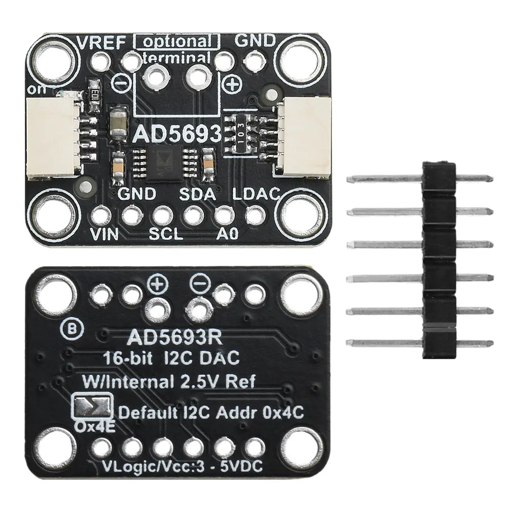
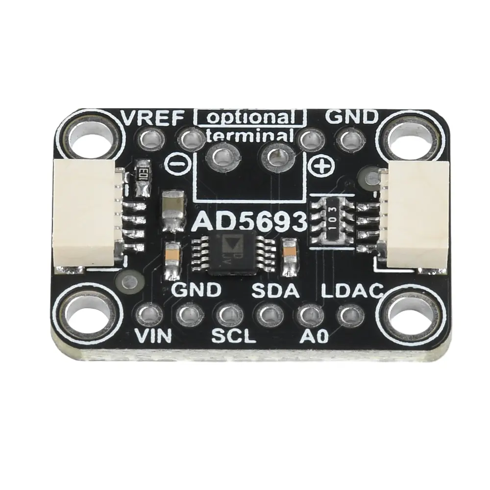
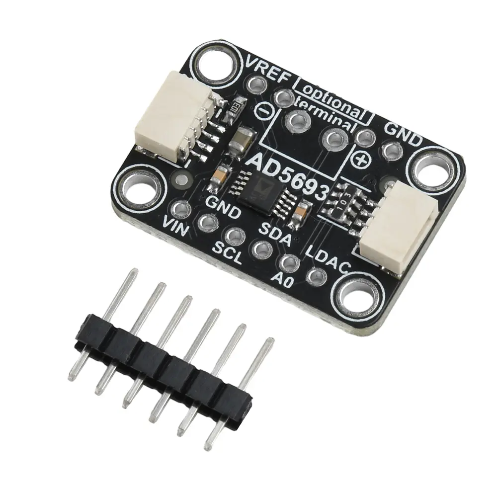
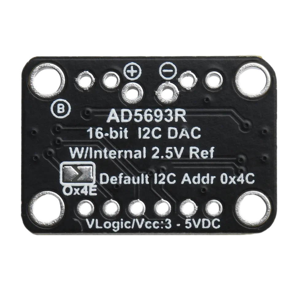
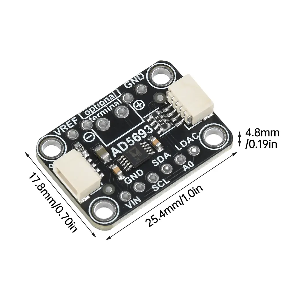
<div class="detailmodule_html"><div class="detail-desc-decorate-richtext"><p>Features:<br/>1. High-precision output: The adapter board utilizes the AD5693R, a 16-bit DAC with an I2C interface and a temperature-compensated 2.5V internal reference to ensure a compact and high-precision output. <br/>2. Dual DAC Compatibility: The I2C DAC adapter module allows you to connect two DACs on a single I2C bus by switching the ADDR/A0 pins or using jumpers on the back to prevent conflicts.<br/>3. Multiple Connection Options: The development board comes with standard 0.1-inch connectors for easy integration with breadboards or perforated boards and four mounting holes for secure installation. <br/>4. Easy Integration: The I2C DAC development board features a custom PCB design with STEMMA QT shape factor with Qwiic I2C-compatible connectors, allowing solderless connections between the development board and the AD5693R, as well as connections to a variety of sensors and accessories using compatible cables. <br/>5. User-Friendly Design: The 16-bit development board is designed for quick setup and ease of use, making it ideal for beginners and experienced developers looking to implement accurate and reliable DAC outputs into their projects.</p><p>The AD5693R breakout board is a 16-bit DAC with an I2C interface and temperature-compensated 2.5V internal reference for compact, high-precision output.<br/>We disconnect the ADDR/A0 pin so you can connect two DACs on a single I2C bus, and simply pull the A0 pin high (or close the jumper on the back) to prevent conflicts. A 6-pin connector for breadboarding is also included. Works with 3.3V or 5V logic, and you can set the output maximum to 2.5V or 5V (2xVref). If you are using a 3.3V supply, you will be able to set the output range to 2.5V or Vin.<br/>We have an easy to use library and tutorial with sample sine wave outputs that can be used with almost any microcontroller or minicomputer with an I2C host.<br/>Comes with a little 0.1-inch standard connector in case you want to use it with a breadboard or perforated board. Four mounting holes for easy installation. there is an optional 3.5 mm terminal location on the PCB, we don't include the 3.5 mm terminals.<br/>To get you up and running quickly, we have customized the PCB with the STEMMA QT form factor to make it easy to connect. The STEMMA QT connectors on both sides are compatible with the Qwiic I2C connectors. This allows you to make a solderless connection between the development board and the AD5693R, or use compatible cables to link it to a variety of other sensors and accessories.</p><p>Parameter:<br/>High relative accuracy (INL): ±2 LSB maximum at 16 bits<br/>Low drift, 2.5 V reference: 2 ppm/°C (typical)<br/>Selectable range output: 2.5 V or 5 V<br/>Total Unadjusted Error (TUE): ±0.06% of maximum FSR value<br/>Misalignment error: ±1.5 mV (max)<br/>Gain error: ±0.05% of FSR max.<br/>Low burr: 0.1 nV/sec<br/>High drive capacity: 20 mA<br/>Operating temperature range: -40°C to +105°C<br/>Product size: 25.2mm x 17.6mm x 4.8mm</p><p>Package include:<br/>1X Module<br/>1X Pin<br/><br/></p></div></div><p><br/></p>
$26.405
$26.405
- Category : Home Improvement
- Brand : z_industry_store Z Industry Store
Colors
Sizes
-
+
<div class="detailmodule_html"><div class="detail-desc-decorate-richtext"><p>Features:<br/>1. High-precision output: The adapter board utilizes the AD5693R, a 16-bit DAC with an I2C interface and a temperature-compensated 2.5V internal reference to ensure a compact and high-precision output. <br/>2. Dual DAC Compatibility: The I2C DAC adapter module allows you to connect two DACs on a single I2C bus by switching the ADDR/A0 pins or using jumpers on the back to prevent conflicts.<br/>3. Multiple Connection Options: The development board comes with standard 0.1-inch connectors for easy integration with breadboards or perforated boards and four mounting holes for secure installation. <br/>4. Easy Integration: The I2C DAC development board features a custom PCB design with STEMMA QT shape factor with Qwiic I2C-compatible connectors, allowing solderless connections between the development board and the AD5693R, as well as connections to a variety of sensors and accessories using compatible cables. <br/>5. User-Friendly Design: The 16-bit development board is designed for quick setup and ease of use, making it ideal for beginners and experienced developers looking to implement accurate and reliable DAC outputs into their projects.</p><p>The AD5693R breakout board is a 16-bit DAC with an I2C interface and temperature-compensated 2.5V internal reference for compact, high-precision output.<br/>We disconnect the ADDR/A0 pin so you can connect two DACs on a single I2C bus, and simply pull the A0 pin high (or close the jumper on the back) to prevent conflicts. A 6-pin connector for breadboarding is also included. Works with 3.3V or 5V logic, and you can set the output maximum to 2.5V or 5V (2xVref). If you are using a 3.3V supply, you will be able to set the output range to 2.5V or Vin.<br/>We have an easy to use library and tutorial with sample sine wave outputs that can be used with almost any microcontroller or minicomputer with an I2C host.<br/>Comes with a little 0.1-inch standard connector in case you want to use it with a breadboard or perforated board. Four mounting holes for easy installation. there is an optional 3.5 mm terminal location on the PCB, we don't include the 3.5 mm terminals.<br/>To get you up and running quickly, we have customized the PCB with the STEMMA QT form factor to make it easy to connect. The STEMMA QT connectors on both sides are compatible with the Qwiic I2C connectors. This allows you to make a solderless connection between the development board and the AD5693R, or use compatible cables to link it to a variety of other sensors and accessories.</p><p>Parameter:<br/>High relative accuracy (INL): ±2 LSB maximum at 16 bits<br/>Low drift, 2.5 V reference: 2 ppm/°C (typical)<br/>Selectable range output: 2.5 V or 5 V<br/>Total Unadjusted Error (TUE): ±0.06% of maximum FSR value<br/>Misalignment error: ±1.5 mV (max)<br/>Gain error: ±0.05% of FSR max.<br/>Low burr: 0.1 nV/sec<br/>High drive capacity: 20 mA<br/>Operating temperature range: -40°C to +105°C<br/>Product size: 25.2mm x 17.6mm x 4.8mm</p><p>Package include:<br/>1X Module<br/>1X Pin<br/><br/></p></div></div><p><br/></p>
Related Product
Browse The Collection of Top Products.