DC12-13.8V 1-5W RF Power Amplifier Board Transceiver Conversion Handheld Power Amplifier Board Intercom Power Amplification
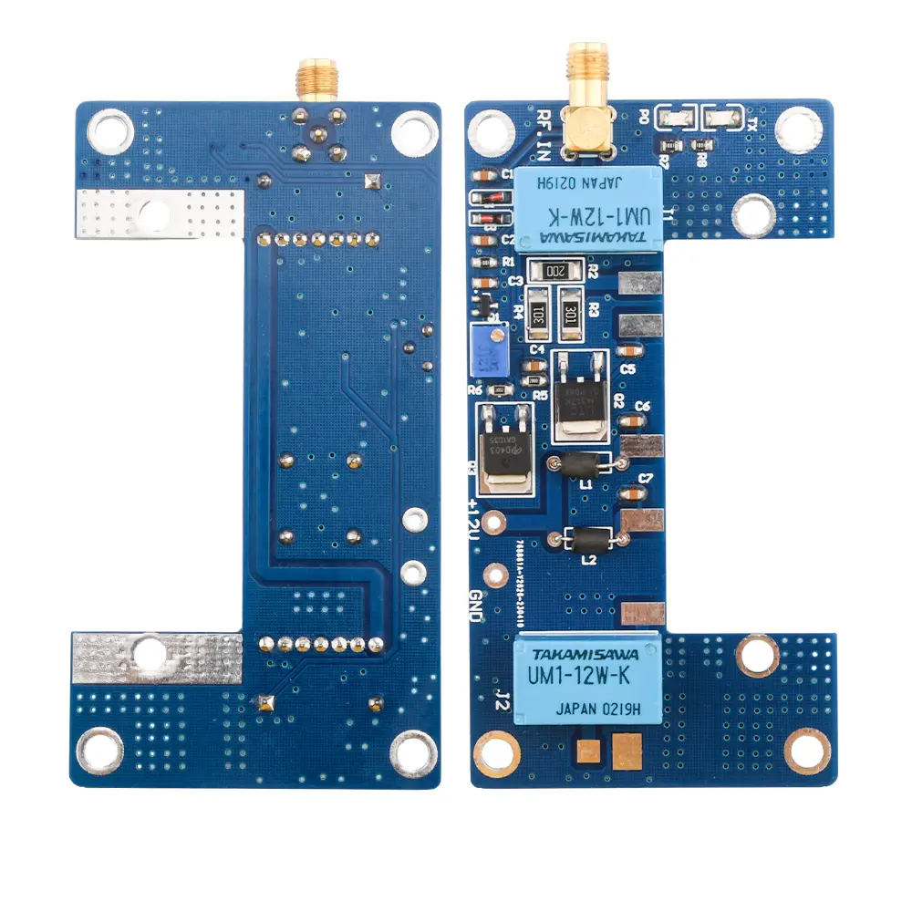
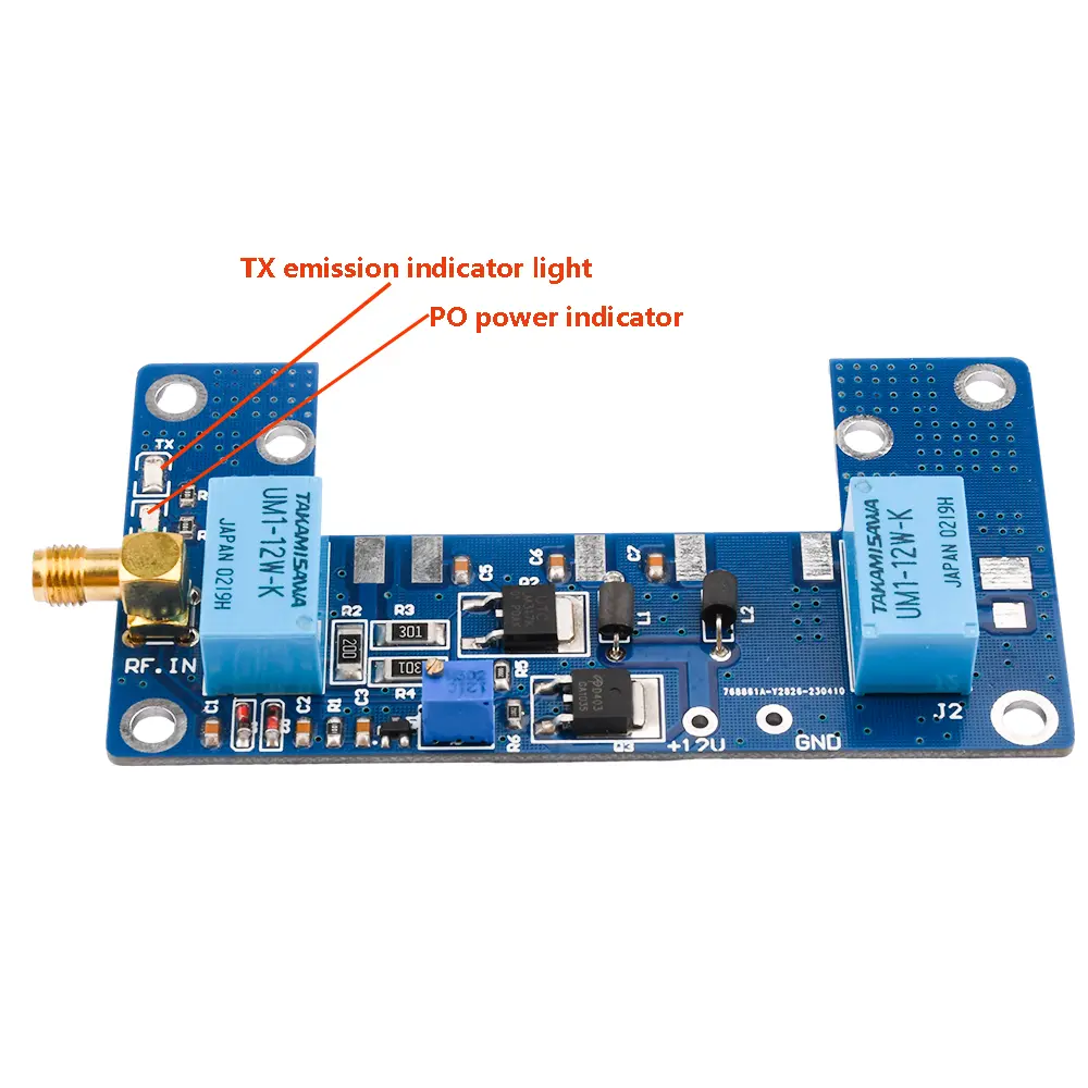
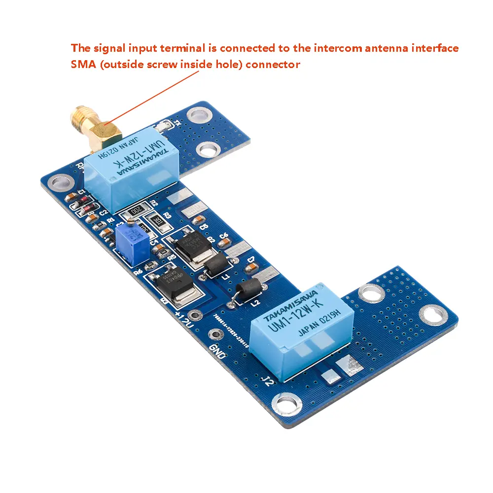
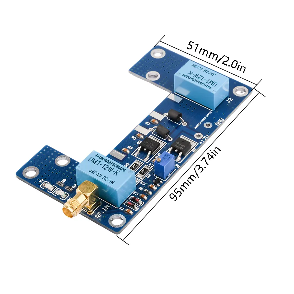
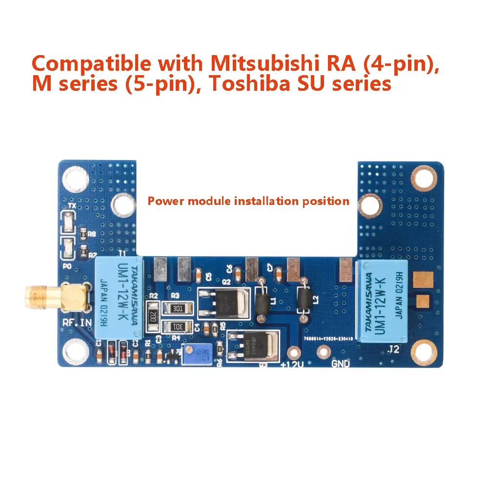
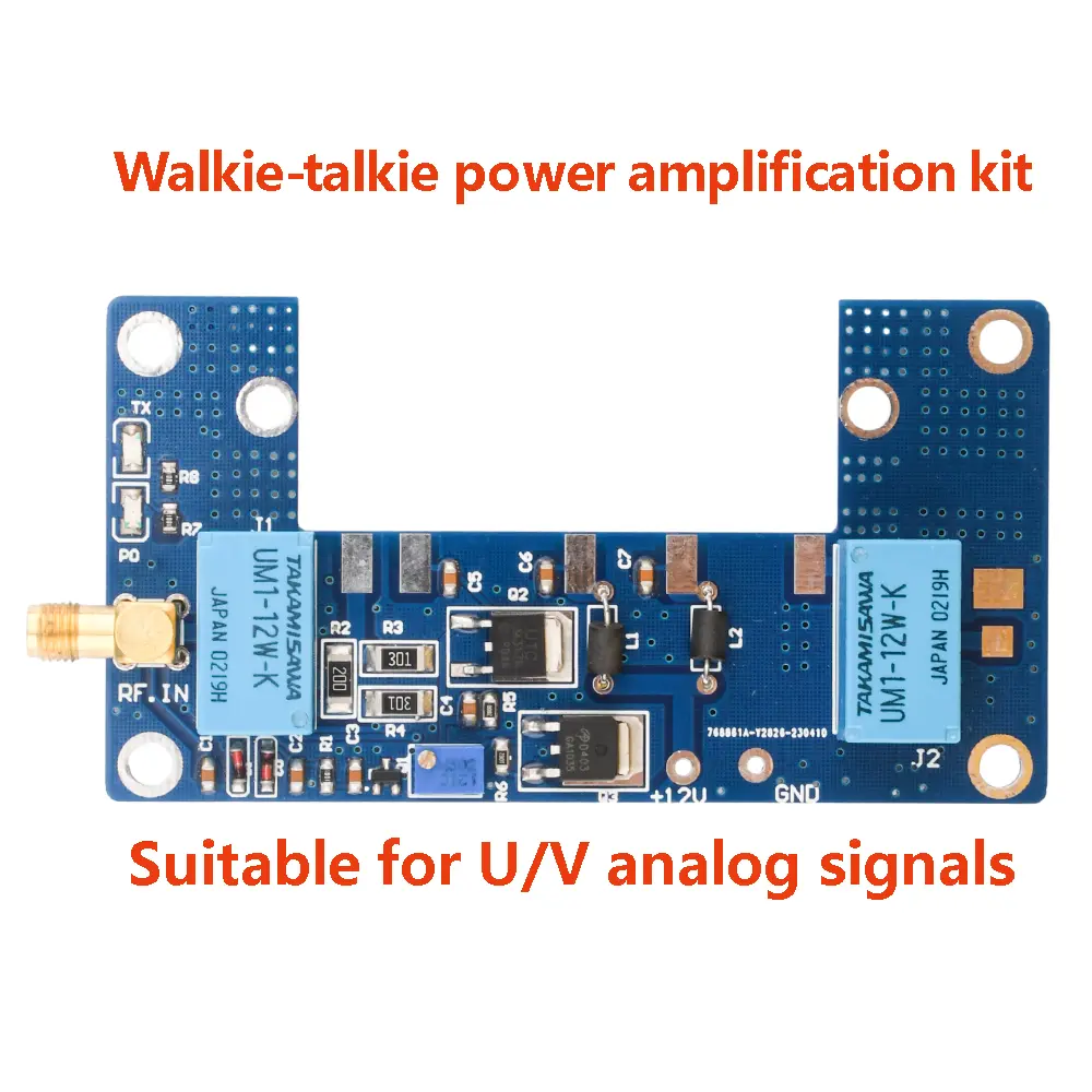
<div class="detailmodule_dynamic"><kse:widget data-widget-type="customText" id="1005000004074434" type="relation"></kse:widget></div><div class="detailmodule_html"><div class="detail-desc-decorate-richtext"><br/><br/><span style="font-size:20px"><strong>Product selling points:</strong></span><br/>1. The board is equipped with an automatic transceiver conversion circuit, which increases the transmission power of the walkie talkie and enables the handheld walkie talkie to have the power of a car mounted station, making communication more distant and voice clearer<br/>2. A power module is required for normal operation<br/>3. The product is made of high-quality materials with guaranteed quality<br/>4. The product has a beautiful appearance and is shipped with an electrostatic bag packaging<br/>5. Perfect for DIY enthusiasts<br/><span style="font-size:20px"><strong><br/>Product technical parameters:</strong></span><br/>Input power: 1-5W<br/>Output power: 10-80W (determined by the installed module)<br/>Input voltage: DC12-13.8V<br/>Operating frequency: 136-170/400-470 (determined by the installed module)<br/>Insertion loss: -1.5DB<br/>Standing wave ratio: ≤ 1.5<br/><br/><span style="font-size:20px"><strong>Product Description:</strong></span><br/>This PCB board is the peripheral circuit of the power module, which needs to be matched with Mitsubishi's RA or M series in order for Toshiba's S series module to function properly. (The power amplifier board does not include the power module and heat sink)<br/><br/>This board is mainly developed for 1-5W handheld walkie talkies, with an automatic transmission and conversion circuit to increase the transmission power of the walkie talkie, thereby enabling the handheld walkie talkie to have the power of a car mounted station, making communication more distant and voice clearer.<br/><br/><span style="font-size:20px"><strong>Installation and debugging methods, precautions:</strong></span><br/>Antennas have a significant impact on communication distance. Please choose a matching antenna and install it correctly.<br/>Before installation, prepare a heat sink with an area larger than the PCB board, and it is recommended to use a thickness of 25MM or more.<br/>Please note that all 6 screws on the board must be tightened, otherwise it may cause damage to the components due to long emission. When tightening the screws, pay attention to the distance between the bottom component pins and the heat sink, and do not let the component pins touch the heat sink to avoid short circuits.<br/>Welding of the power output end feeder, please provide the feeder yourself.<br/>Before debugging the RA series module, all pins must be disconnected from the PCB board and can only be soldered on after voltage adjustment.<br/>The working voltage of the second pin (VGG) on the left side of the RA module is between 2.3 and 3.3V (within this range, the higher the voltage, the greater the output power, which may self excite or burn the power module). Before debugging, connect the walkie talkie to the PCB board, prepare a multimeter, turn the multimeter to the DC voltage range, and then connect the red lead to the second pin (VGG) of the module on the PCB board, the black lead to the negative electrode, and then press the transmitter button of the walkie talkie, Then adjust the blue Potentiometer on the board (it becomes smaller about 15 turns clockwise) to read the voltage value on the multimeter.<br/><br/>The working voltage of M or S series modules is 10-14V, which can be directly installed on the PCB board and adjusted to 10-12V.<br/>1: Electric indicator light (red), emission indicator light (green)<br/>2: 1-5W power input (external screw and internal hole SMA)<br/>3: DC12-13.8V power interface<br/>4: Adjust the voltage and power of the second pin (VGG) of the module, and the voltage will decrease by about 15 turns clockwise<br/>5: Power output interface (upper negative and lower positive)<br/><br/><span style="font-size:20px"><strong>Shipping list:</strong></span><br/>Module X1<br/><br/></div></div><br/>
$51.26
$49.265
- Category : Consumer Electronics
- Brand : diy_electronics_module_999_store DIY Electronics Module 999 Store
Colors
Sizes
-
+
<div class="detailmodule_dynamic"><kse:widget data-widget-type="customText" id="1005000004074434" type="relation"></kse:widget></div><div class="detailmodule_html"><div class="detail-desc-decorate-richtext"><br/><br/><span style="font-size:20px"><strong>Product selling points:</strong></span><br/>1. The board is equipped with an automatic transceiver conversion circuit, which increases the transmission power of the walkie talkie and enables the handheld walkie talkie to have the power of a car mounted station, making communication more distant and voice clearer<br/>2. A power module is required for normal operation<br/>3. The product is made of high-quality materials with guaranteed quality<br/>4. The product has a beautiful appearance and is shipped with an electrostatic bag packaging<br/>5. Perfect for DIY enthusiasts<br/><span style="font-size:20px"><strong><br/>Product technical parameters:</strong></span><br/>Input power: 1-5W<br/>Output power: 10-80W (determined by the installed module)<br/>Input voltage: DC12-13.8V<br/>Operating frequency: 136-170/400-470 (determined by the installed module)<br/>Insertion loss: -1.5DB<br/>Standing wave ratio: ≤ 1.5<br/><br/><span style="font-size:20px"><strong>Product Description:</strong></span><br/>This PCB board is the peripheral circuit of the power module, which needs to be matched with Mitsubishi's RA or M series in order for Toshiba's S series module to function properly. (The power amplifier board does not include the power module and heat sink)<br/><br/>This board is mainly developed for 1-5W handheld walkie talkies, with an automatic transmission and conversion circuit to increase the transmission power of the walkie talkie, thereby enabling the handheld walkie talkie to have the power of a car mounted station, making communication more distant and voice clearer.<br/><br/><span style="font-size:20px"><strong>Installation and debugging methods, precautions:</strong></span><br/>Antennas have a significant impact on communication distance. Please choose a matching antenna and install it correctly.<br/>Before installation, prepare a heat sink with an area larger than the PCB board, and it is recommended to use a thickness of 25MM or more.<br/>Please note that all 6 screws on the board must be tightened, otherwise it may cause damage to the components due to long emission. When tightening the screws, pay attention to the distance between the bottom component pins and the heat sink, and do not let the component pins touch the heat sink to avoid short circuits.<br/>Welding of the power output end feeder, please provide the feeder yourself.<br/>Before debugging the RA series module, all pins must be disconnected from the PCB board and can only be soldered on after voltage adjustment.<br/>The working voltage of the second pin (VGG) on the left side of the RA module is between 2.3 and 3.3V (within this range, the higher the voltage, the greater the output power, which may self excite or burn the power module). Before debugging, connect the walkie talkie to the PCB board, prepare a multimeter, turn the multimeter to the DC voltage range, and then connect the red lead to the second pin (VGG) of the module on the PCB board, the black lead to the negative electrode, and then press the transmitter button of the walkie talkie, Then adjust the blue Potentiometer on the board (it becomes smaller about 15 turns clockwise) to read the voltage value on the multimeter.<br/><br/>The working voltage of M or S series modules is 10-14V, which can be directly installed on the PCB board and adjusted to 10-12V.<br/>1: Electric indicator light (red), emission indicator light (green)<br/>2: 1-5W power input (external screw and internal hole SMA)<br/>3: DC12-13.8V power interface<br/>4: Adjust the voltage and power of the second pin (VGG) of the module, and the voltage will decrease by about 15 turns clockwise<br/>5: Power output interface (upper negative and lower positive)<br/><br/><span style="font-size:20px"><strong>Shipping list:</strong></span><br/>Module X1<br/><br/></div></div><br/>