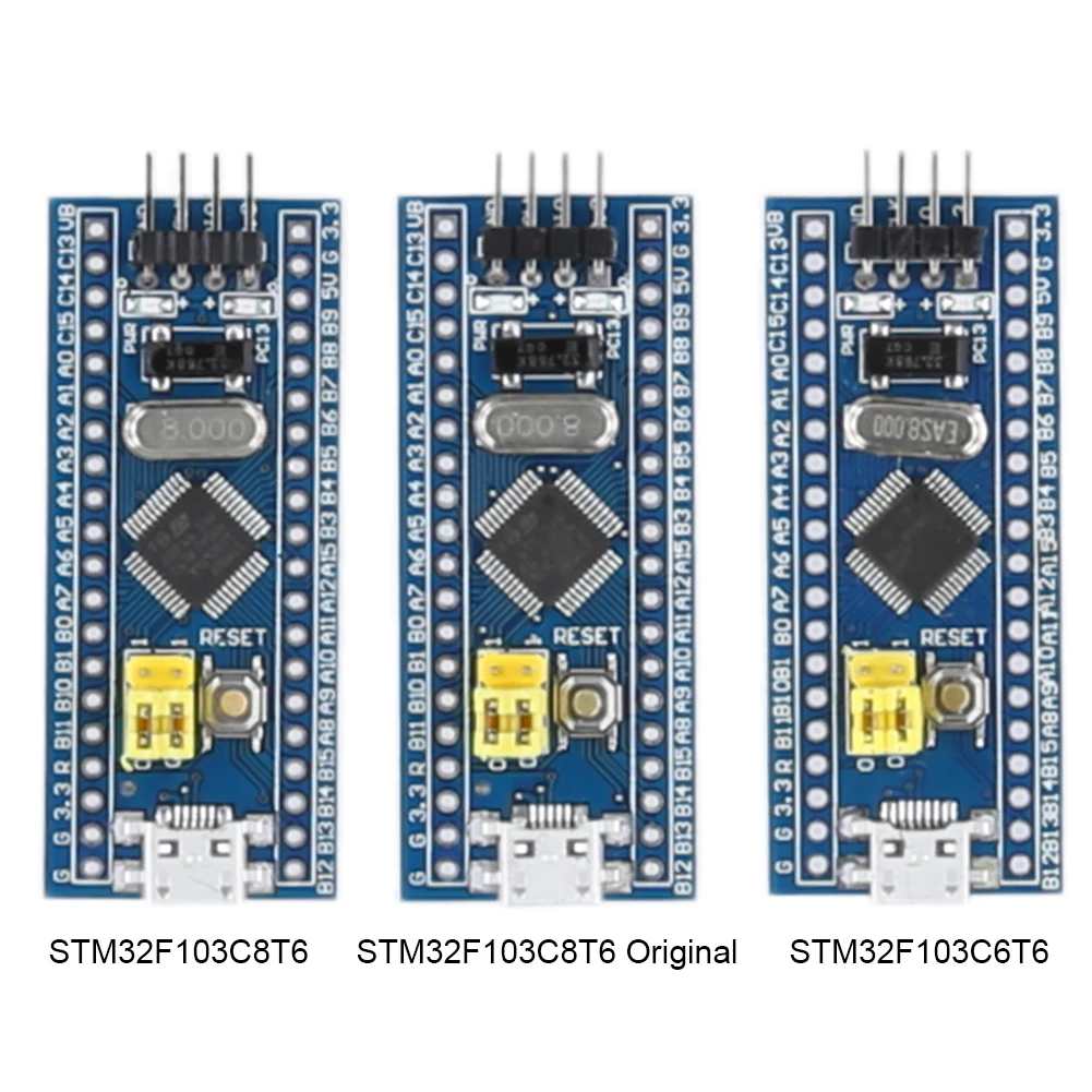
STM32F103C8T6/C6T6 Minimum System Development Board Module ARM STM32 Microcontroller Development Board Module for Arduino
<div class="detailmodule_html"><div class="detail-desc-decorate-richtext"><table class="ke-zeroborder" width="100%" cellspacing="0" cellpadding="0" border="0" style="font-family:"">
<tbody>
<tr>
<td>
<div>
<span style="color:#171A1D;font-family:"font-size:14px;background-color:#FFFFFF;"></span><br />
</div>
<div style="padding:15px;border:1px solid #AEAEAE;">
<p>
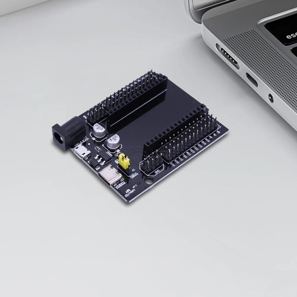
<span style="color:black;font-family:inherit;font-size:12px;">STM32F103C8T6/C6T6 Minimum System Development Board Module ARM STM32 Microcontroller Development Board Module for Arduino<br />
<strong>Features:</strong><br />
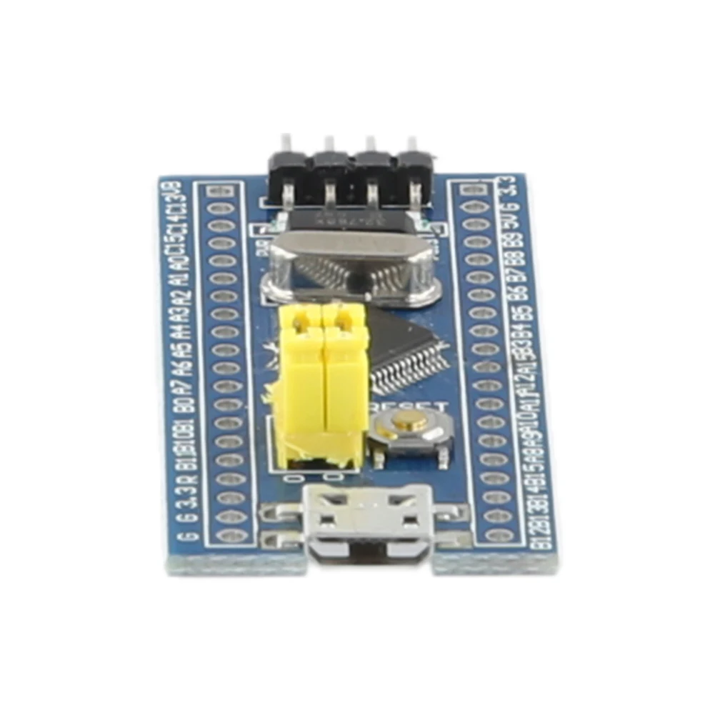
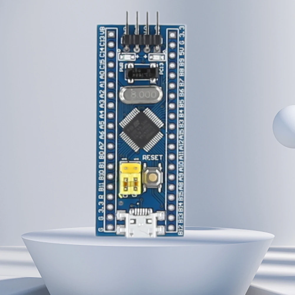
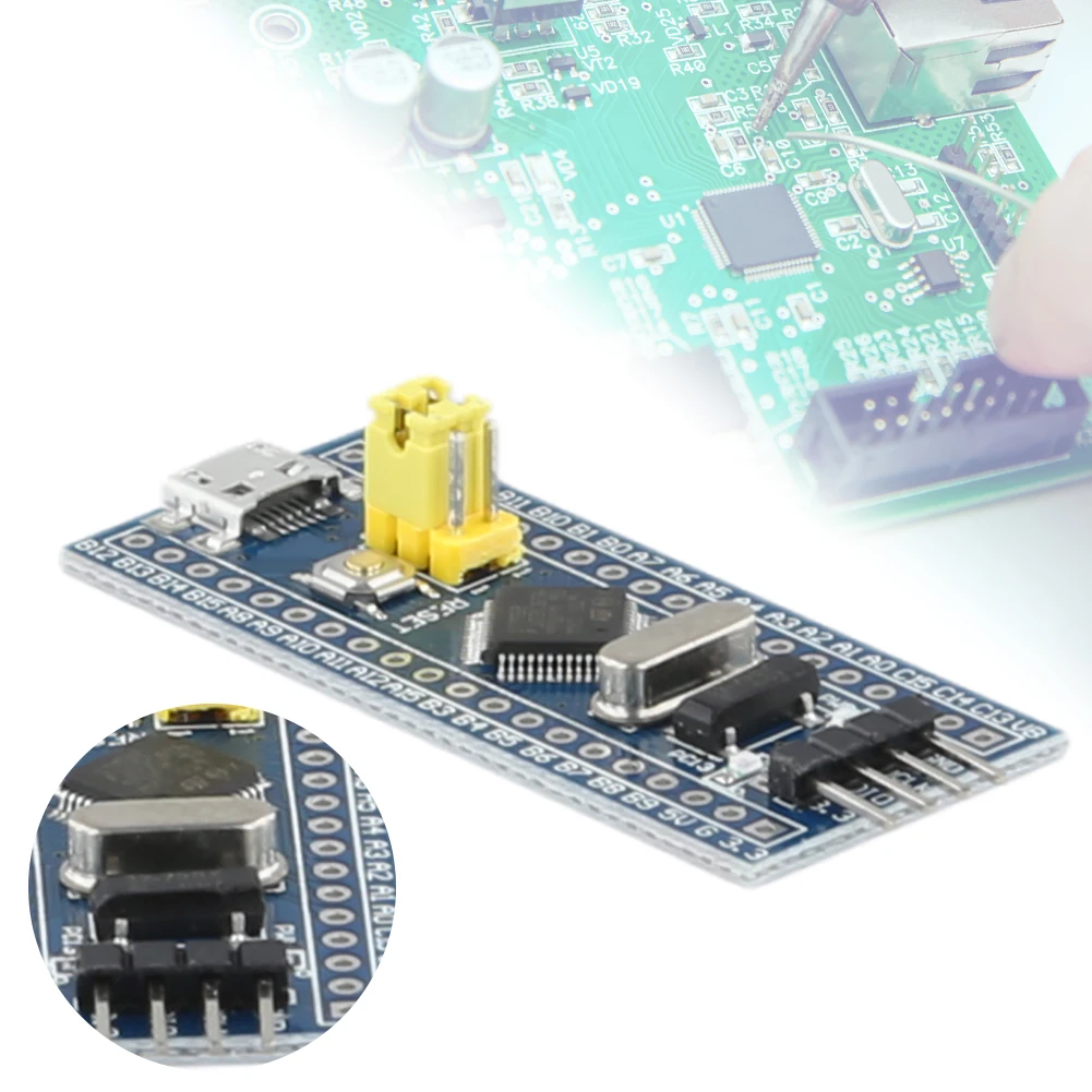
<strong>1.Advanced Core Performance:</strong> Our minimum system development board module is built around a powerful STM32 chip with a 64K Byte Flash and 20KByte SRAM, encapsulated in an LQFP package with 48 pins, ensuring swift and efficient operations for complex tasks and applications.<br />
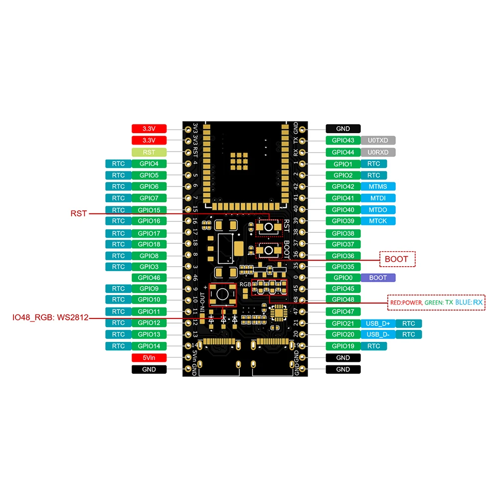
<strong>2.Versatile Connectivity Options:</strong> Featuring 2x SPI, 3x USART, 2x I2C, and 1x CAN for flexible connectivity, along with 37x I/O ports, this minimum core learning board provides a wide range of options for connecting to various devices, making it ideal for intricate electronic projects and system developments.<br />
<strong>3.Precision Debugging and Programming:</strong> The microcontroller core board supports JTAG/SWD interface for debugging, programming, and IAP with ease, complemented by a Micro USB interface for power and communication, and a USART1 interface, providing users with a hassle-free and speedy setup for their development needs.<br />
<strong>4.Enhanced Power Management:</strong> With a RT9193 3.3V regulator ensuring a stable output of up to 300mA and power supply interfaces for both 5V and 3.3V, the ARM system board processor also features a power LED (PWR) and a user LED (PC13) for straightforward power status and operation indication, enhancing the reliability and user-friendliness of the device.<br />
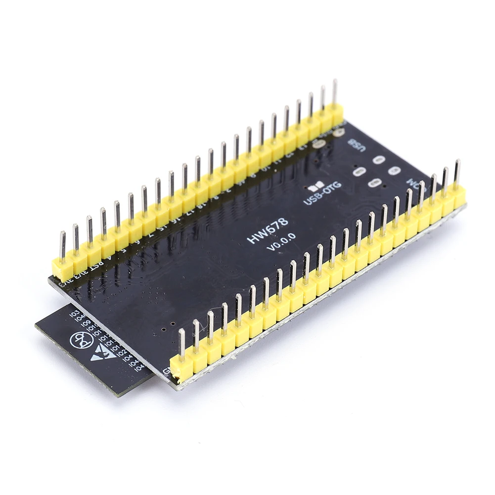
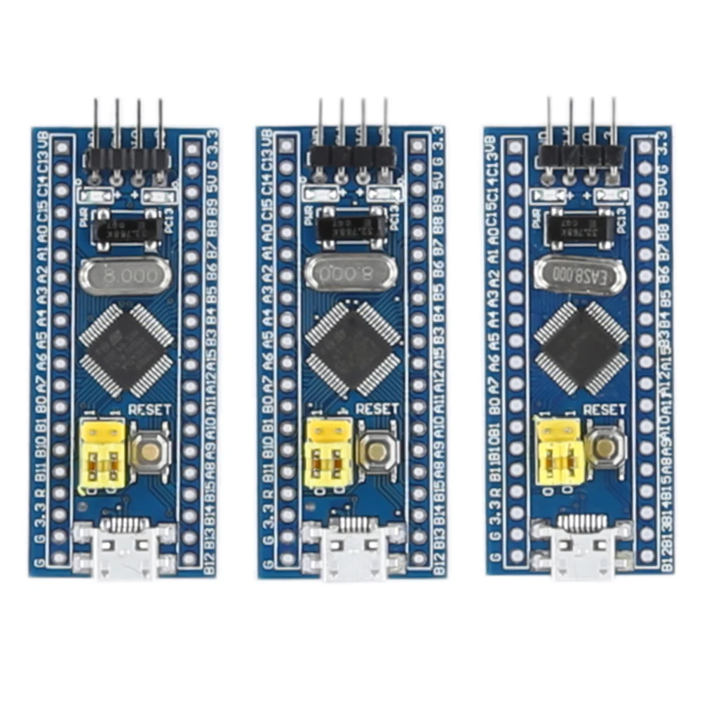
<strong>5.Customizable Physical Configuration:</strong> The ARM development module comes with un-soldered pin headers, allowing users to choose the soldering direction that best fits their specific use case. This customizable approach ensures that the board can easily adapt to a variety of setups and projects, from educational environments to advanced engineering applications.<br />
</span>
</p><br/><br/><span><strong>Specification:</strong></span><br />
<span>Origin: Mainland China</span><br />
<span>Type: Module</span><br />
<span>Condition: New</span><br />
Chip Description:<br />
Package Type: LQFP<br />
Number of Pins: 48<br />
Core: Cortex-M3<br />
Operating Frequency: 72MHz<br />
Storage Resources: 64K Byte Flash, 20KByte SRAM<br />
Interface Resources: 2x SPI, 3x USART, 2x I2C, 1x CAN, 37x I/O ports<br />
Analog-to-Digital Conversion: 2x ADC (12-bit/16-channel)<br />
Timers: 3 general-purpose timers and 1 advanced timer<br />
Debug Download: Support JTAG/SWD debug interface download, support IAP<br />
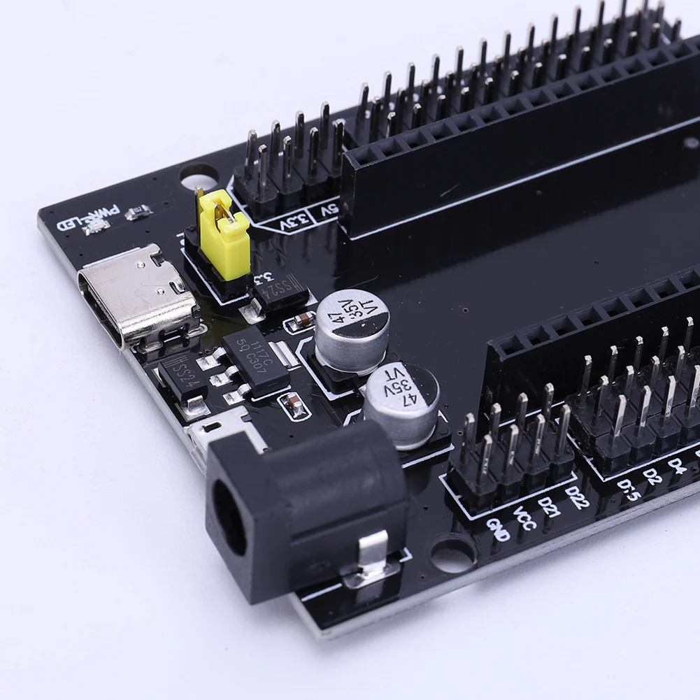
RT9193: 3.3V voltage regulator chip, maximum output 300mA<br />
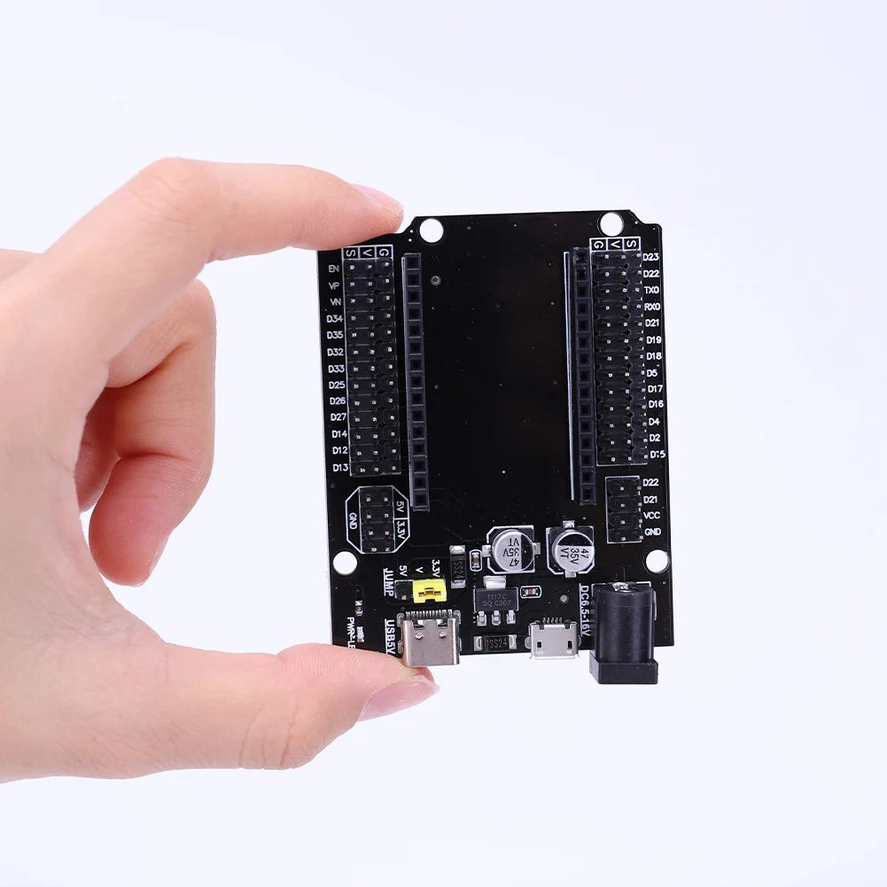
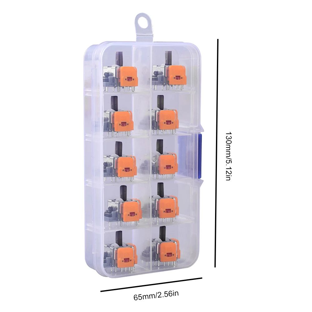
Product Size: 54.00x23.00x12.00mm/2.11*0.9*0.47in<br />
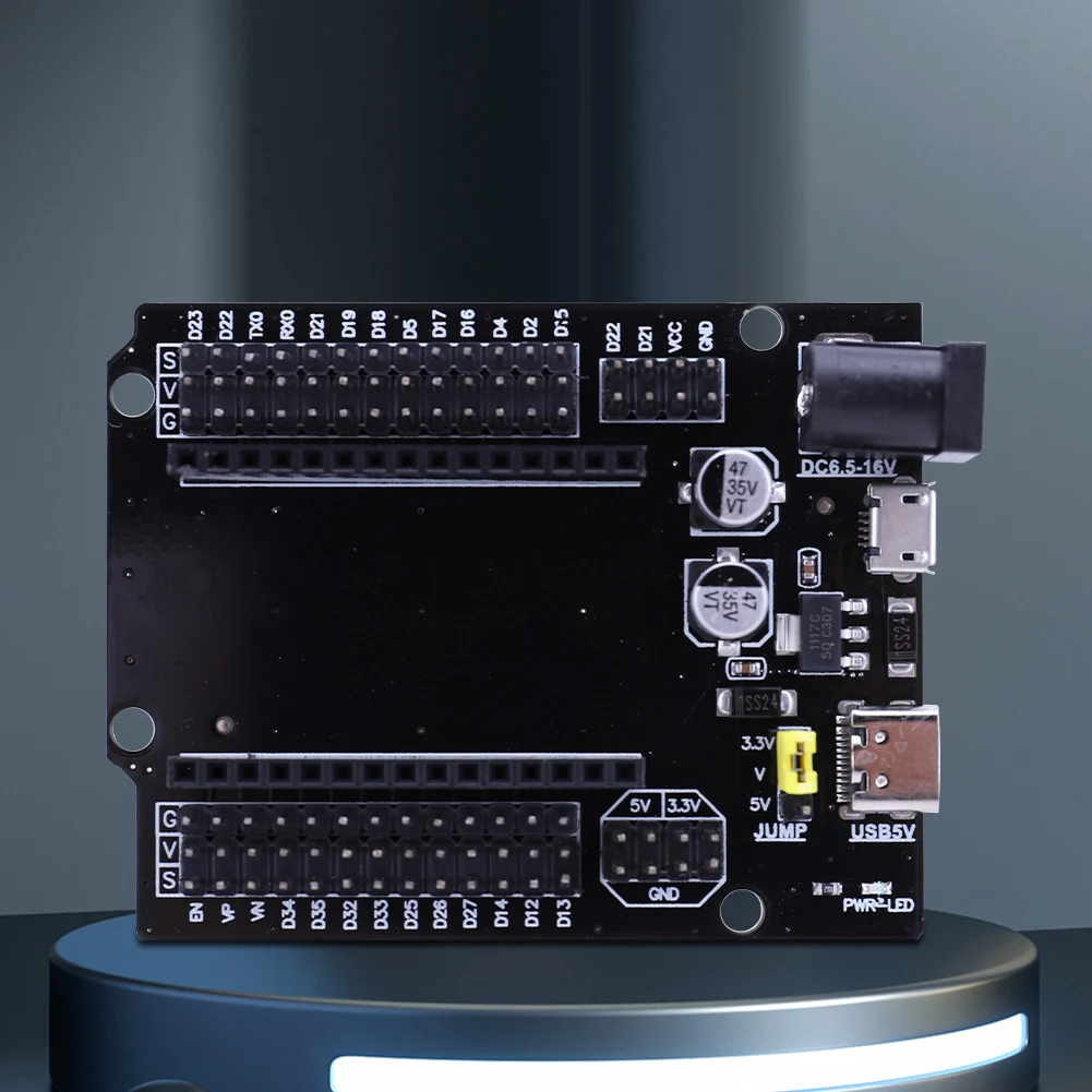
Interface Description:<br />
1. SWD interface: support simulation, download and debugging.<br />
2. Mirco USB interface: power supply and USB communication, does not support download.<br />
3. USART1 interface: you can use USART1 to download the program, or use USART1 for communication.<br />
4. MCU pin interface: Pin out all I/O port pins, convenient to connect with peripherals.<br />
5. 5V and 3.3V power input/output interface: commonly used for external power supply, or common ground processing with other modules.<br />
Other Device Description:<br />
1. Power LED (PWR): power indicator status, can determine whether the power supply is stable.<br />
2. User LED (PC13): convenient for I/O output testing or indicating program operation.<br />
3. Start jump to select programming mode: (1, user flash memory 2, SRAM 3, system memory).<br />
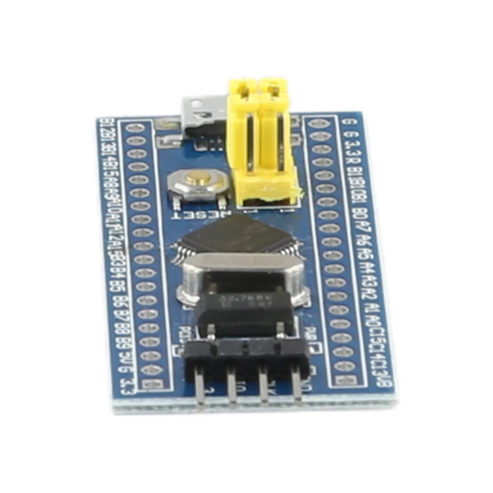
4. Reset button: used to reset the user program of the chip.<br />
5. 8M crystal oscillator: can set the frequency so that the system main frequency is 72MHz.<br />
6. 32.768KHz crystal: can be used for built-in RTC, or for calibration.<br />
<br />
<p>
<strong>Note:</strong><br />
Due to the different monitor and light effect, the actual color of the item might be slightly different from the color showed on the pictures. Thank you!<br />
Please allow 1-2cm measuring deviation due to manual measurement.
</p>
<br /><br><p>
<span style="color:black;font-family:inherit;font-size:12px;">STM32F103C8T6/C6T6 Minimum System Development Board Module ARM STM32 Microcontroller Development Board Module for Arduino<br />
<strong>Features:</strong><br />
<strong>1.Advanced Core Performance:</strong> Our minimum system development board module is built around a powerful STM32 chip with a 64K Byte Flash and 20KByte SRAM, encapsulated in an LQFP package with 48 pins, ensuring swift and efficient operations for complex tasks and applications.<br />
<strong>2.Versatile Connectivity Options:</strong> Featuring 2x SPI, 3x USART, 2x I2C, and 1x CAN for flexible connectivity, along with 37x I/O ports, this minimum core learning board provides a wide range of options for connecting to various devices, making it ideal for intricate electronic projects and system developments.<br />
<strong>3.Precision Debugging and Programming:</strong> The microcontroller core board supports JTAG/SWD interface for debugging, programming, and IAP with ease, complemented by a Micro USB interface for power and communication, and a USART1 interface, providing users with a hassle-free and speedy setup for their development needs.<br />
<strong>4.Enhanced Power Management:</strong> With a RT9193 3.3V regulator ensuring a stable output of up to 300mA and power supply interfaces for both 5V and 3.3V, the ARM system board processor also features a power LED (PWR) and a user LED (PC13) for straightforward power status and operation indication, enhancing the reliability and user-friendliness of the device.<br />
<strong>5.Customizable Physical Configuration:</strong> The ARM development module comes with un-soldered pin headers, allowing users to choose the soldering direction that best fits their specific use case. This customizable approach ensures that the board can easily adapt to a variety of setups and projects, from educational environments to advanced engineering applications.<br />
</span>
</p><br/><br/><span><strong>Specification:</strong></span><br />
<span>Origin: Mainland China</span><br />
<span>Type: Module</span><br />
<span>Condition: New</span><br />
Chip Description:<br />
Package Type: LQFP<br />
Number of Pins: 48<br />
Core: Cortex-M3<br />
Operating Frequency: 72MHz<br />
Storage Resources: 64K Byte Flash, 20KByte SRAM<br />
Interface Resources: 2x SPI, 3x USART, 2x I2C, 1x CAN, 37x I/O ports<br />
Analog-to-Digital Conversion: 2x ADC (12-bit/16-channel)<br />
Timers: 3 general-purpose timers and 1 advanced timer<br />
Debug Download: Support JTAG/SWD debug interface download, support IAP<br />
RT9193: 3.3V voltage regulator chip, maximum output 300mA<br />
Product Size: 54.00x23.00x12.00mm/2.11*0.9*0.47in<br />
Interface Description:<br />
1. SWD interface: support simulation, download and debugging.<br />
2. Mirco USB interface: power supply and USB communication, does not support download.<br />
3. USART1 interface: you can use USART1 to download the program, or use USART1 for communication.<br />
4. MCU pin interface: Pin out all I/O port pins, convenient to connect with peripherals.<br />
5. 5V and 3.3V power input/output interface: commonly used for external power supply, or common ground processing with other modules.<br />
Other Device Description:<br />
1. Power LED (PWR): power indicator status, can determine whether the power supply is stable.<br />
2. User LED (PC13): convenient for I/O output testing or indicating program operation.<br />
3. Start jump to select programming mode: (1, user flash memory 2, SRAM 3, system memory).<br />
4. Reset button: used to reset the user program of the chip.<br />
5. 8M crystal oscillator: can set the frequency so that the system main frequency is 72MHz.<br />
6. 32.768KHz crystal: can be used for built-in RTC, or for calibration.<br />
<br />
<p>
<strong>Note:</strong><br />
Due to the different monitor and light effect, the actual color of the item might be slightly different from the color showed on the pictures. Thank you!<br />
Please allow 1-2cm measuring deviation due to manual measurement.
</p>
<br /><br />
</div>
<br />
<div>
</div>
<div style="padding:15px;border:1px solid #AEAEAE;">
1*Minimum System Development Board<br>1*Minimum System Development Board<br>1*Minimum System Development Board<br>1*Minimum System Development Board<br />
</div>
<br />
<div style="text-align:center;">
</div>
<br />
<div>
</div>
<div style="padding:15px;border:1px solid #AEAEAE;">
<span style="color:#171A1D;font-family:"font-size:14px;background-color:#FFFFFF;"></span><br />
</div>
<br />
<br />
</td>
</tr>
</tbody>
</table></div></div>
$8.645
$5.315
- Category : Electronic Components & Supplies
- Brand : outdoor_riding4_store Outdoor Riding4 Store
Colors
Sizes
-
+
<div class="detailmodule_html"><div class="detail-desc-decorate-richtext"><table class="ke-zeroborder" width="100%" cellspacing="0" cellpadding="0" border="0" style="font-family:"">
<tbody>
<tr>
<td>
<div>
<span style="color:#171A1D;font-family:"font-size:14px;background-color:#FFFFFF;"></span><br />
</div>
<div style="padding:15px;border:1px solid #AEAEAE;">
<p>
<span style="color:black;font-family:inherit;font-size:12px;">STM32F103C8T6/C6T6 Minimum System Development Board Module ARM STM32 Microcontroller Development Board Module for Arduino<br />
<strong>Features:</strong><br />
<strong>1.Advanced Core Performance:</strong> Our minimum system development board module is built around a powerful STM32 chip with a 64K Byte Flash and 20KByte SRAM, encapsulated in an LQFP package with 48 pins, ensuring swift and efficient operations for complex tasks and applications.<br />
<strong>2.Versatile Connectivity Options:</strong> Featuring 2x SPI, 3x USART, 2x I2C, and 1x CAN for flexible connectivity, along with 37x I/O ports, this minimum core learning board provides a wide range of options for connecting to various devices, making it ideal for intricate electronic projects and system developments.<br />
<strong>3.Precision Debugging and Programming:</strong> The microcontroller core board supports JTAG/SWD interface for debugging, programming, and IAP with ease, complemented by a Micro USB interface for power and communication, and a USART1 interface, providing users with a hassle-free and speedy setup for their development needs.<br />
<strong>4.Enhanced Power Management:</strong> With a RT9193 3.3V regulator ensuring a stable output of up to 300mA and power supply interfaces for both 5V and 3.3V, the ARM system board processor also features a power LED (PWR) and a user LED (PC13) for straightforward power status and operation indication, enhancing the reliability and user-friendliness of the device.<br />
<strong>5.Customizable Physical Configuration:</strong> The ARM development module comes with un-soldered pin headers, allowing users to choose the soldering direction that best fits their specific use case. This customizable approach ensures that the board can easily adapt to a variety of setups and projects, from educational environments to advanced engineering applications.<br />
</span>
</p><br/><br/><span><strong>Specification:</strong></span><br />
<span>Origin: Mainland China</span><br />
<span>Type: Module</span><br />
<span>Condition: New</span><br />
Chip Description:<br />
Package Type: LQFP<br />
Number of Pins: 48<br />
Core: Cortex-M3<br />
Operating Frequency: 72MHz<br />
Storage Resources: 64K Byte Flash, 20KByte SRAM<br />
Interface Resources: 2x SPI, 3x USART, 2x I2C, 1x CAN, 37x I/O ports<br />
Analog-to-Digital Conversion: 2x ADC (12-bit/16-channel)<br />
Timers: 3 general-purpose timers and 1 advanced timer<br />
Debug Download: Support JTAG/SWD debug interface download, support IAP<br />
RT9193: 3.3V voltage regulator chip, maximum output 300mA<br />
Product Size: 54.00x23.00x12.00mm/2.11*0.9*0.47in<br />
Interface Description:<br />
1. SWD interface: support simulation, download and debugging.<br />
2. Mirco USB interface: power supply and USB communication, does not support download.<br />
3. USART1 interface: you can use USART1 to download the program, or use USART1 for communication.<br />
4. MCU pin interface: Pin out all I/O port pins, convenient to connect with peripherals.<br />
5. 5V and 3.3V power input/output interface: commonly used for external power supply, or common ground processing with other modules.<br />
Other Device Description:<br />
1. Power LED (PWR): power indicator status, can determine whether the power supply is stable.<br />
2. User LED (PC13): convenient for I/O output testing or indicating program operation.<br />
3. Start jump to select programming mode: (1, user flash memory 2, SRAM 3, system memory).<br />
4. Reset button: used to reset the user program of the chip.<br />
5. 8M crystal oscillator: can set the frequency so that the system main frequency is 72MHz.<br />
6. 32.768KHz crystal: can be used for built-in RTC, or for calibration.<br />
<br />
<p>
<strong>Note:</strong><br />
Due to the different monitor and light effect, the actual color of the item might be slightly different from the color showed on the pictures. Thank you!<br />
Please allow 1-2cm measuring deviation due to manual measurement.
</p>
<br /><br><p>
<span style="color:black;font-family:inherit;font-size:12px;">STM32F103C8T6/C6T6 Minimum System Development Board Module ARM STM32 Microcontroller Development Board Module for Arduino<br />
<strong>Features:</strong><br />
<strong>1.Advanced Core Performance:</strong> Our minimum system development board module is built around a powerful STM32 chip with a 64K Byte Flash and 20KByte SRAM, encapsulated in an LQFP package with 48 pins, ensuring swift and efficient operations for complex tasks and applications.<br />
<strong>2.Versatile Connectivity Options:</strong> Featuring 2x SPI, 3x USART, 2x I2C, and 1x CAN for flexible connectivity, along with 37x I/O ports, this minimum core learning board provides a wide range of options for connecting to various devices, making it ideal for intricate electronic projects and system developments.<br />
<strong>3.Precision Debugging and Programming:</strong> The microcontroller core board supports JTAG/SWD interface for debugging, programming, and IAP with ease, complemented by a Micro USB interface for power and communication, and a USART1 interface, providing users with a hassle-free and speedy setup for their development needs.<br />
<strong>4.Enhanced Power Management:</strong> With a RT9193 3.3V regulator ensuring a stable output of up to 300mA and power supply interfaces for both 5V and 3.3V, the ARM system board processor also features a power LED (PWR) and a user LED (PC13) for straightforward power status and operation indication, enhancing the reliability and user-friendliness of the device.<br />
<strong>5.Customizable Physical Configuration:</strong> The ARM development module comes with un-soldered pin headers, allowing users to choose the soldering direction that best fits their specific use case. This customizable approach ensures that the board can easily adapt to a variety of setups and projects, from educational environments to advanced engineering applications.<br />
</span>
</p><br/><br/><span><strong>Specification:</strong></span><br />
<span>Origin: Mainland China</span><br />
<span>Type: Module</span><br />
<span>Condition: New</span><br />
Chip Description:<br />
Package Type: LQFP<br />
Number of Pins: 48<br />
Core: Cortex-M3<br />
Operating Frequency: 72MHz<br />
Storage Resources: 64K Byte Flash, 20KByte SRAM<br />
Interface Resources: 2x SPI, 3x USART, 2x I2C, 1x CAN, 37x I/O ports<br />
Analog-to-Digital Conversion: 2x ADC (12-bit/16-channel)<br />
Timers: 3 general-purpose timers and 1 advanced timer<br />
Debug Download: Support JTAG/SWD debug interface download, support IAP<br />
RT9193: 3.3V voltage regulator chip, maximum output 300mA<br />
Product Size: 54.00x23.00x12.00mm/2.11*0.9*0.47in<br />
Interface Description:<br />
1. SWD interface: support simulation, download and debugging.<br />
2. Mirco USB interface: power supply and USB communication, does not support download.<br />
3. USART1 interface: you can use USART1 to download the program, or use USART1 for communication.<br />
4. MCU pin interface: Pin out all I/O port pins, convenient to connect with peripherals.<br />
5. 5V and 3.3V power input/output interface: commonly used for external power supply, or common ground processing with other modules.<br />
Other Device Description:<br />
1. Power LED (PWR): power indicator status, can determine whether the power supply is stable.<br />
2. User LED (PC13): convenient for I/O output testing or indicating program operation.<br />
3. Start jump to select programming mode: (1, user flash memory 2, SRAM 3, system memory).<br />
4. Reset button: used to reset the user program of the chip.<br />
5. 8M crystal oscillator: can set the frequency so that the system main frequency is 72MHz.<br />
6. 32.768KHz crystal: can be used for built-in RTC, or for calibration.<br />
<br />
<p>
<strong>Note:</strong><br />
Due to the different monitor and light effect, the actual color of the item might be slightly different from the color showed on the pictures. Thank you!<br />
Please allow 1-2cm measuring deviation due to manual measurement.
</p>
<br /><br />
</div>
<br />
<div>
</div>
<div style="padding:15px;border:1px solid #AEAEAE;">
1*Minimum System Development Board<br>1*Minimum System Development Board<br>1*Minimum System Development Board<br>1*Minimum System Development Board<br />
</div>
<br />
<div style="text-align:center;">
</div>
<br />
<div>
</div>
<div style="padding:15px;border:1px solid #AEAEAE;">
<span style="color:#171A1D;font-family:"font-size:14px;background-color:#FFFFFF;"></span><br />
</div>
<br />
<br />
</td>
</tr>
</tbody>
</table></div></div>
Related Product
Browse The Collection of Top Products.